Bottom line: A laser marking machine for automotive VIN numbers should not be selected by wattage or marking speed alone. Before buying, confirm that laser marking is an accepted method for the target vehicle and market, test the actual chassis material and surface condition, agree on the required mark geometry and durability, and prove that the VIN sent to the laser matches the vehicle record.
For a passenger-car body line, truck chassis, motorcycle frame or off-road vehicle frame, the practical challenge is usually the same: the VIN must be in the approved location, remain readable, be difficult to alter or remove, and match the correct vehicle throughout production and later service.
This guide explains seven requirements to settle before ordering a VIN laser marking system. It is written for manufacturing engineers, quality managers, production managers and purchasing teams who need a process they can test and document—not just a machine that can engrave metal.
Important: VIN requirements vary by jurisdiction and vehicle category. Confirm the applicable regulation and the vehicle manufacturer’s approved process before treating laser marking as an authorized replacement for stamping or another established method.
What Does VIN Traceability Actually Require?
A VIN is not just a line of characters engraved into metal. It is the link between a physical vehicle and its manufacturing, inspection, registration and service records. If the wrong VIN is marked on the right chassis, the laser may have worked perfectly while the production process has failed.
For a VIN marking project, separate three things:
- Physical mark: the characters are in the approved location and meet the required appearance, geometry, permanence and readability criteria.
- Data integrity: the VIN loaded into the marking controller belongs to the vehicle currently in the station.
- Record integrity: the production system can retrieve the marking event, inspection result and relevant vehicle record later.
These are related, but they are not interchangeable. A camera can confirm that characters are visible; it cannot, by itself, prove that the characters belong to the correct vehicle. A database can store the correct VIN; it cannot prove that the laser actually marked it correctly.
For international programs, ISO 3779 addresses the content and structure of a vehicle identification number. In the United States, NHTSA explains that VINs are governed by 49 CFR Part 565 and consist of 17 characters. These references are starting points, not a substitute for checking the complete rules that apply to your vehicle category and market.
Reference: ISO 3779 — Road vehicles, VIN content and structure and NHTSA VIN interpretations.
Requirement 1: Confirm the Legal Requirements and Approved Marking Location
Start with the vehicle program, not the laser catalogue. Before asking whether a 30W or 50W machine is suitable, ask the compliance or homologation team which VIN marking method is approved for the target vehicle, where the VIN must be placed, and what the finished mark must look like.
For example, a passenger-car body line may have a defined identification area, while a commercial vehicle frame may have different access constraints and a different production sequence. A motorcycle frame, trailer or off-road vehicle may fall under a different set of requirements. Do not assume that a process approved for one vehicle type is automatically acceptable for another.
What to confirm before machine selection
- The destination market and applicable vehicle category.
- The approved physical marking location and orientation.
- Whether laser engraving is permitted for this VIN application, or whether stamping or another method is specified.
- The required character height, spacing, line layout and permitted character set.
- Required permanence, legibility, tamper resistance and inspection records.
- Whether the mark must be applied before or after a particular welding, coating or assembly operation.
Practical solution: Ask the customer to supply the approved VIN drawing, applicable specification and acceptance criteria before a sample test begins. If these documents are unavailable, treat the project as a feasibility study—not a production-ready compliance solution.
Common mistake: assuming that a deep laser engraving automatically meets legal requirements. Depth alone does not establish compliance, tamper resistance or acceptance by a vehicle authority.
Requirement 2: Test the Actual Chassis Material and Surface Condition
“Steel chassis” is not a sufficient test specification. The result can change with steel grade, surface finish, mill scale, rust, oil, weld spatter, coating, curvature and the condition of the marking area.
Consider three typical production situations:
- Welded carbon-steel frame: the marking area may be close to welds, heat-affected zones or uneven surfaces. Fixture access and focus stability need to be checked.
- Painted or coated chassis: the laser may remove coating rather than create the intended mark in the base metal. If the coating is later repaired or the mark is exposed to corrosion, the result may not meet the requirement.
- Aluminum structural component: the alloy and surface treatment can change the contrast and material-removal behavior. Do not transfer a steel recipe to aluminum without testing.
How to conduct a useful sample test
- Use a representative production part or a coupon with the same material, finish and coating condition.
- Mark the actual approved VIN layout—not just a company logo or a few large characters.
- Record the laser source, rated power, lens, focus position, pulse settings where adjustable, scan speed, hatch spacing, number of passes and fixture setup.
- Inspect the characters under the customer’s normal viewing and inspection conditions.
- Run any required corrosion, coating, cleaning, abrasion or other durability tests under the customer’s approved procedure.
- Repeat the test on parts representing the expected range of surface conditions.
Acceptance evidence: a sample report that identifies the material and finish, machine configuration, parameters, mark photographs, measurement results and any durability test results. A photograph alone is not enough to establish long-term performance.
Limit: a successful test on a clean, flat steel coupon does not prove the same process will work on an oily, curved, coated or production-welded chassis.
Requirement 3: Define Marking Depth, Character Geometry and Durability
For chassis VIN marking, the goal is not simply to make the characters dark. The mark must meet the customer’s approved requirements for legibility, permanence and resistance to alteration without creating unacceptable damage to the structural component.
There is no universal laser depth that can safely be recommended for every chassis. The required depth, character dimensions and acceptable material removal must come from the vehicle specification and the validated process. A deeper mark is not automatically a better mark: excessive material removal may be unacceptable on a structural area, while a shallow surface change may fail a durability requirement.
What the engineering team should specify
- Character height, stroke width, spacing and overall marking area.
- Required depth or other measurable mark characteristics, where specified.
- Maximum permitted material removal or restrictions on structural damage.
- Required contrast and readability after the relevant downstream processes.
- How the mark will be inspected and what constitutes a pass or fail.
Do not use a supplier’s maximum advertised engraving depth as the target process depth. Published maximum values may refer to different materials, small test areas or multiple passes, and they may not reflect the cycle time or surface quality needed for a full VIN.
Practical solution: establish a parameter window rather than approving one attractive sample. Test a suitable range of settings, inspect the character edges and material surface, then repeat the best candidate on multiple representative parts. Keep the final parameters under process control.
Important limitation: if the vehicle manufacturer has not defined a permissible depth or validated marking method, the equipment supplier should not invent one. The vehicle engineering and compliance teams must approve the acceptance criteria.
Requirement 4: Prevent Incorrect VIN Data from Reaching the Laser
This is one of the most important—and often overlooked—parts of the project. A machine can produce perfectly shaped characters and still create a serious traceability failure if the wrong VIN is sent to it.
In manual production, an operator may select a file or type a number. On a high-volume line, a controller may receive a vehicle record from a PLC, MES or another production system. Either approach needs a defined method for preventing mismatches, duplicate assignments and accidental re-marking.
A sensible data-control sequence
- Read the vehicle identifier from the approved source, such as the production order or authorized vehicle record.
- Check that the record is valid and belongs to the current station cycle.
- Show or confirm the VIN before marking when required by the risk assessment.
- Trigger the laser only when the correct vehicle or fixture is present and the cycle is authorized.
- Record the VIN, job or vehicle reference, timestamp, station identity, recipe version and marking result.
- Prevent a completed VIN from being unintentionally assigned to another vehicle or re-marked without authorization.
For a semi-automatic station, a barcode scan, operator confirmation and controlled job selection may be adequate, depending on the risk and customer requirements. For a fully automated line, a PLC handshake and production-system integration may be more appropriate.
Buyer question: “How does the system know that this VIN belongs to this chassis—not the chassis that was in the station one cycle ago?” Ask the supplier to demonstrate the actual workflow with a wrong record, a missing record and a repeated record.
Acceptance evidence: a documented interface description and test results for valid, invalid, missing, duplicate and interrupted-cycle data. Do not assume that a standard desktop laser controller automatically includes MES integration or VIN-level error-proofing.
Requirement 5: Control Positioning on Large, Curved or Hard-to-Reach Frames
A standard benchtop marking machine is designed around a known working distance and marking field. An automotive chassis is a very different workpiece: it may be long, heavy, uneven, partly assembled and difficult to bring to the laser.
In many projects, the fixture and positioning method matter as much as the laser source. If the marking head cannot reach the approved location at the correct focus distance, increasing laser power will not solve the problem.
Choose the positioning method for the real production layout
- Fixed station with a dedicated fixture: suitable when the chassis arrives in a repeatable position and the marking area is accessible.
- Adjustable or multi-axis fixture: useful when several frame variants share a station but have different marking locations.
- Robot-assisted marking: worth evaluating when the chassis is large, access is restricted or several marking positions are required.
- Vision-assisted positioning: can help locate a defined feature or compensate for part-position variation, but requires validation against the actual surface and lighting conditions.
For example, a truck frame supplier may need to mark different chassis lengths and wheelbase variants. A fixture designed for one model could place the next model outside the usable marking field. The solution may be a configurable fixture, a different optical setup or a robot—not necessarily a higher-wattage laser.
Questions to test on the actual chassis
- Can the laser head reach the approved marking position without collision?
- Is the surface within the required focus tolerance across the complete VIN?
- Can the fixture hold the chassis securely despite its mass and dimensional variation?
- Will welding seams, brackets, cables or installed components obstruct the beam?
- Can operators load and unload the part safely and repeatably?
Acceptance evidence: a fit-up trial using the real chassis or a geometrically representative fixture, with documented access, focus and repeat-positioning checks.
Limit: a standard 110 × 110 mm marking field is a common reference configuration, not a promise that every chassis can be marked in one setup. The actual lens, working distance, head position and part geometry must be confirmed.
Requirement 6: Verify Every Mark and Keep Inspection Evidence
Visual inspection is useful, but “the characters look clear” is not a complete acceptance method for an automotive identification process. The inspection method should match the approved drawing, customer quality plan and applicable regulatory requirements.
Depending on the specification, inspection may include character geometry, location, legibility, material condition, mark depth and resistance to downstream processes. If the customer requires a particular measurement method, use that method rather than substituting an informal visual check.
Build an inspection plan around the failure modes
- Missing or incomplete character: inspect the entire VIN, not only the first and last characters.
- Wrong character: compare the marked VIN with the authorized production record.
- Poor contrast or damaged edges: inspect under the specified lighting and viewing conditions.
- Wrong position or orientation: compare the mark with the approved datum and location drawing.
- Insufficient permanence: run the required durability tests, not just an immediate post-marking check.
A camera may be suitable for character presence, position or optical character recognition when properly validated. However, camera inspection should not be described as a guarantee of regulatory compliance unless the full inspection method and acceptance criteria have been approved.
If the project also uses a QR code or Data Matrix for internal logistics, treat that code as an additional data carrier. It does not automatically replace the required physical VIN, and scanning a code does not prove that a VIN mark meets its own requirements.
Records worth retaining
- Vehicle or production-order identifier.
- VIN data sent to the controller and, where available, confirmation of the final marked characters.
- Station ID, timestamp and machine recipe version.
- Inspection result, rejection reason and rework authorization.
- Relevant images, measurement results and approved sample-test reports.
- Machine maintenance or calibration records where required by the quality plan.
Practical solution: agree on the inspection record format before commissioning. A folder of unlabeled photos is not a reliable traceability system; each record needs to connect to the relevant vehicle and production event.
Requirement 7: Prove the Full Cycle Time and Traceability Chain
Laser scanner speed is not the same as finished vehicles per hour. A VIN cycle may include vehicle positioning, fixture clamping, data transfer, focus or vision checks, marking, inspection, record confirmation and station release.
For example, if a station needs 12 seconds for positioning and clamping, 8 seconds for data and interlock checks, 15 seconds for marking, and 5 seconds for inspection and release, the total cycle is 40 seconds—not 15 seconds. These figures are only an illustrative calculation, not a JQ Laser performance claim.
At 40 seconds per vehicle, the theoretical single-station rate is 90 vehicles per hour before accounting for downtime, shift changes, rejected parts, maintenance or upstream and downstream constraints. Actual accepted output will be lower unless the process has been demonstrated otherwise.
Run a production acceptance test
- Use representative chassis models, material conditions and production data.
- Run repeated cycles, not just one successful demonstration.
- Measure the complete station cycle from the defined start event to the defined release event.
- Record first-pass acceptance, marking errors, data errors, interruptions and rework.
- Test restart behavior after a power interruption, communication fault or rejected part.
- Confirm that every accepted mark has the required production record and every rejected cycle is handled safely.
For a semi-automatic station, the operator may provide the positioning and data confirmation. For a high-volume line, the project may need a PLC, sensors, an industrial camera, guarding, a fixture and a validated production-system interface. Those elements affect cost and delivery time, so they should be specified in the quotation.
Buyer tip: write the acceptance test around the real production target. “High speed” is not a measurable acceptance criterion. A defined cycle-time target, first-pass acceptance target, traceability record and fault-recovery test are much more useful.
Which Fiber Laser Configuration Should You Evaluate for VIN Marking?
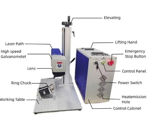
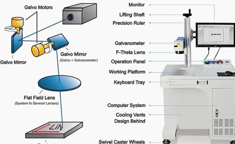
JQ Laser’s published fiber laser range includes 20W, 30W, 50W and 100W configurations. The published reference specification lists a typical 1064 nm wavelength, a standard 110 × 110 mm marking field, optional larger fields, air cooling for common configurations and a reference marking speed of up to approximately 7,000 mm/s. The final specification depends on the selected source, optics, controller, machine structure and application.
These are equipment reference values—not a validated VIN recipe. A machine that can mark a small steel coupon quickly may need a different configuration for a full VIN on a large chassis, especially if the mark must be deep, the surface is uneven or the station must be automated.
| Configuration | When to evaluate it | What must be proved | Main limitation |
|---|---|---|---|
| 20W fiber | Initial feasibility trials or applications where the required material removal and cycle time are modest. | Required mark geometry, depth or other acceptance criteria, legibility and cycle time on the actual material. | May not meet the required material-removal rate or cycle target for a demanding VIN process. |
| 30W fiber | General metal marking where additional process capacity over a lower-power system may be useful. | Same full VIN acceptance test, including character quality and production cycle. | Rated power alone does not predict the final cycle time or compliance. |
| 50W fiber | Applications where test results show that greater material-removal capacity or a shorter marking cycle is needed. | Depth, surface condition, character edges, heat effects and complete cycle time. | Higher power does not solve poor access, incorrect data or unstable focus. |
| 100W fiber | Demanding industrial applications where the approved process needs greater laser capacity and the station is designed for it. | Process window, thermal and surface effects, safety, integration and the target production rate. | Higher equipment cost and capacity may be unnecessary if a lower-power system already meets the validated target. |
Do not assume a 50W machine is automatically the correct choice for chassis VIN marking. The appropriate configuration is the lowest-risk system that meets the approved mark requirements, cycle time, access constraints and traceability needs with repeatable evidence.
See the JQ Laser fiber laser marking machine and automatic laser marking machine pages for the published product range. Confirm the final bill of materials and interface requirements in the project quotation.
VIN Laser Marking Procurement Checklist: 7 Checks Before You Order
Use this checklist during supplier evaluation. Each item states when it applies, how to verify it and what it does not prove.
| Check | Applicable conditions | Evidence / test method | Limitations |
|---|---|---|---|
| 1. Regulatory approval | Every VIN project, especially when changing from an existing marking method. | Approved drawing, applicable rule or customer specification, written process approval. | A supplier statement or sample photo is not regulatory approval. |
| 2. Material and surface test | Different steel grades, aluminum alloys, coatings, weld conditions or suppliers. | Sample report using representative parts and recorded parameters. | One clean coupon does not represent all production surfaces. |
| 3. Mark geometry and permanence | Where character dimensions, depth, location or durability are controlled. | Measurement against the approved drawing and required durability test report. | Maximum advertised depth does not prove a compliant VIN mark. |
| 4. VIN data integrity | Manual entry, barcode-triggered jobs, PLC interfaces or MES-connected lines. | Demonstrate correct, incorrect, missing and duplicate VIN handling; inspect event logs. | Correct data in the database does not prove the correct data was physically marked. |
| 5. Positioning and access | Large chassis, curved frames, model variation or restricted access. | Fit-up trial on the real part or representative fixture; verify focus and repeat positioning. | A standard marking field does not guarantee access to the required chassis location. |
| 6. Inspection and records | Programs with defined quality gates, audits or long-term traceability requirements. | Approved inspection method, sample records, rejection logic and record retrieval test. | A basic camera or scanner may not meet the customer’s full inspection requirement. |
| 7. Production acceptance | All projects with a required cycle time or automated production interface. | Repeated full-cycle test, first-pass acceptance report, fault-recovery test and interface sign-off. | A single demonstration or scanner-speed figure does not prove stable production output. |
Documents to request from the supplier
- Configuration-specific quotation and bill of materials, including laser source, rated power, lens, controller and any enclosure or fixture.
- Application sample report with the actual VIN layout and representative chassis material.
- Marking parameter sheet and agreed acceptance criteria.
- Station layout and access assessment, if the chassis is large or difficult to position.
- Interface list for PLC, sensors, camera, barcode reader or MES connection, as applicable.
- Factory acceptance test (FAT) plan, installation requirements, operator training and service arrangements.
- Spare-parts list, maintenance guidance and a defined escalation route for production downtime.
Comparison: Laser Marking, Mechanical Stamping and Labels
The right process depends on the vehicle specification and approved manufacturing route. This table is a procurement comparison, not a claim that laser marking can replace stamping in every jurisdiction.
| Factor | Fiber laser marking | Mechanical stamping / punching | Adhesive label |
|---|---|---|---|
| Mark creation | Uses a focused laser to change or remove material at the surface. | Uses mechanical force to deform or displace material. | Applies printed or encoded information to a label substrate. |
| Tooling and setup | Can change the marking file electronically; fixture and positioning still matter. | May require dedicated tooling and force control for the part. | Requires label printing, application and control of label stock. |
| Large or awkward chassis | May need a custom fixture, extended reach, robot or vision positioning. | May need a suitable press, reaction support and access to the marking area. | May be easy to apply but depends on approved label location and substrate. |
| Process validation | Must validate mark geometry, permanence, material effects and safety. | Must validate character form, depth, material deformation and the approved process. | Must validate adhesion, readability and environmental durability. |
| Data integration | Can be integrated with controlled job data, PLCs and production systems if configured. | May require separate data control if the process uses variable VIN content. | Can support variable printing but needs controls against wrong-label application. |
| Key purchasing risk | Assuming the laser recipe or power rating guarantees compliance. | Assuming existing tooling suits every chassis design or material. | Assuming a label meets the vehicle program’s permanent identification rules. |
Decision rule: first establish the method allowed by the vehicle program and applicable rules. Then compare the validated process cost, access, cycle time, maintenance and traceability performance. Do not choose a method on equipment price alone.
How JQ Laser Can Support a VIN Marking Feasibility Study
JQ Laser supplies fiber laser marking systems in 20W, 30W, 50W and 100W configurations, with a typical 1064 nm wavelength and a standard 110 × 110 mm marking field on published configurations. Optional fields and automation depend on the selected machine design.
For a chassis VIN project, the useful starting point is not a generic machine quote. It is a defined application brief that allows the marking process and station design to be evaluated against the actual workpiece and production target.
Send these details for a meaningful technical review
- Vehicle type and destination market.
- Chassis material, coating and surface condition.
- Approved VIN drawing, character dimensions and marking location.
- Required depth or other mark acceptance criteria, if specified.
- Chassis photographs and access dimensions, plus a drawing or CAD file where available.
- Required cycle time and daily or hourly production volume.
- Manual, semi-automatic or fully automatic operation.
- Required PLC, vision, barcode, MES or other interface.
- Inspection and durability tests that the customer requires.
With this information, the configuration can be assessed more responsibly: whether a standard fiber laser is sufficient, whether a higher-power source is worth testing, whether a custom fixture is needed, and whether the project requires a separate automation and inspection package.
Request a VIN marking feasibility review: Contact JQ Laser. Include the material, approved drawing, required cycle time and destination market so the initial discussion can focus on the real application.
Related pages: VIN Code Marking Solution, Automatic Laser Marking Machine, Product Traceability Solution and Fiber Laser Marking Machine.
Technical note: Product specifications and laser suitability must be confirmed for the quoted configuration and the customer’s actual workpiece. No equipment specification alone guarantees legal approval, permanent readability or acceptance of a VIN marking process.
Frequently Asked Questions
1. Can a fiber laser mark VIN numbers directly on an automotive chassis?
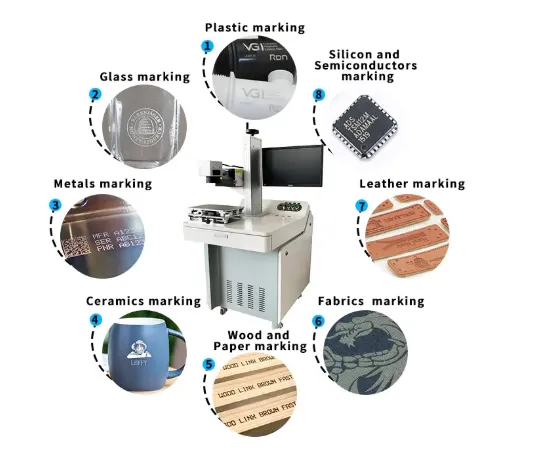
A fiber laser can mark suitable metal surfaces, including selected steel and aluminum parts. Whether it is an acceptable method for a particular VIN application depends on the vehicle category, destination market, approved process and the results of material and durability testing.
2. Is a 20W, 30W, 50W or 100W laser best for chassis VIN marking?
There is no universal best wattage. JQ Laser lists 20W, 30W, 50W and 100W fiber configurations. Select a candidate based on the required mark characteristics, actual chassis material, access, cycle-time target and automation needs, then validate it on representative parts.
3. What marking depth is required for a VIN?
Do not use a generic depth as a universal requirement. Follow the applicable vehicle specification and approved process. The required mark must be tested for legibility, permanence and any limits on material removal or structural damage.
4. Can laser marking be integrated with a vehicle production line?
Yes, an appropriately designed system can be configured with fixtures, sensors, PLC control, vision positioning and production-system interfaces. These features are configuration-dependent and should be included in the quotation and acceptance test.
5. How can a factory prevent the wrong VIN from being marked?
Use controlled VIN data from an authorized source, verify that it matches the vehicle at the station, prevent unauthorized duplicate or repeat jobs, and retain the marking and inspection event records. Test missing, invalid, duplicated and interrupted-cycle data before production release.
6. Does a camera inspection system prove VIN compliance?
Not automatically. A camera may verify character presence, position or readability if the inspection method is validated. Compliance also depends on the applicable rules, approved marking process and other acceptance criteria.
7. What should be included in a VIN laser marking supplier quote?
Request the laser source and power, lens and marking field, controller, fixture, guarding, positioning method, software and interface scope, inspection equipment, sample-test results, FAT criteria, installation and training scope, spare parts and service arrangements.
Technical References and Further Reading
- ISO 3779:2009 — Road vehicles, Vehicle Identification Number (VIN), content and structure. Defines the VIN content and structure framework; it is not a laser process specification.
- NHTSA — VIN interpretations. Explains aspects of United States VIN requirements under 49 CFR Part 565.
- Commission Implementing Regulation (EU) 2021/535, consolidated text. Consult the provisions applicable to the vehicle category and approval route.
- JQ Laser — Fiber Laser Marking Machine. Published power options, wavelength, typical marking field and configuration notes.
- JQ Laser — VIN Code Marking Solution. Related application overview.
- JQ Laser — Automatic Laser Marking Machine. Related automation equipment information.
Reference limitation: the regulatory references above are starting points for compliance review. The vehicle manufacturer or authorized compliance team must identify the complete current requirements that apply to the specific vehicle and destination market.