In the modern landscape of precision engineering, industrial traceability, and permanent component branding, the fiber laser marking machine has established itself as an irreplaceable cornerstone technology. From automotive part numbering and aerospace compliance branding to the micro-engraving of delicate medical devices, fiber laser systems deliver unparalleled marking speeds, permanent contrast, and exceptional operational lifespans exceeding 100,000 hours without regular maintenance.
However, for factory procurement officers, production line engineers, and global distributors, navigating the technical nuances of fiber laser technology can be daunting. Achieving the perfect mark requires a deep, mathematically precise understanding of laser physics, material interactions, and software configuration.
This comprehensive technical guide serves as an authoritative textbook for optimizing your laser operations, balancing software parameters, understanding the mechanical anatomy of laser sources, and executing strategic sourcing methodologies to maximize return on investment (ROI).
Table of Contents
The Core Physics of Fiber Laser Technology
To fully appreciate the efficacy of a fiber laser marker, one must understand the quantum mechanics and optical physics that govern its beam generation. Unlike CO2 lasers which rely on gas mixtures, or traditional YAG lasers that utilize flashlamp-pumped solid crystal rods, a fiber laser generates its beam through an entirely solid-state architecture.
1.1 Active Medium and Rare-Earth Doping
The heart of the fiber laser oscillator is an optical fiber doped with trivalent rare-earth ions, most commonly Ytterbium (Yb³⁺). Ytterbium is selected because its energy levels allow for highly efficient absorption of pump light in the 915–980 nm spectrum, emitting a highly coherent laser beam at a fundamental wavelength of 1064 nm (near-infrared spectrum).
The optical amplification process follows standard laser kinetics:
- Optical Pumping: High-power semiconductor laser diodes inject pump light into the outer cladding of the double-clad doped fiber.
- Population Inversion: The Yb³⁺ ions absorb the pump photons, elevating electrons to a short-lived, high-energy state.
- Stimulated Emission: As these electrons drop back to their ground state, they release photons that match the phase, frequency, and direction of the oscillating light wave trapped within the fiber core.
- Resonant Cavity: Instead of conventional mirrors, the resonant cavity is formed by Fiber Bragg Gratings (FBGs) written directly into the fiber core, reflecting specific wavelengths while allowing the highly amplified 1064 nm beam to exit.
+------------------+     +------------------------+     +------------------------+

|  Pump Diodes     | --> | Active Ytterbium Fiber | --> | Fiber Bragg Gratings   | --> Output Beam
|  (915-980 nm)    |     | (Population Inversion) |     | (Resonant Cavity)      |     (1064 nm)
+------------------+     +------------------------+     +------------------------+
1.2 Beam Quality Factors (M
1.2 Beam Quality Factors (M²) and Rayleigh Length
In high-precision material processing, beam focusability determines the energy density (W/cm²) at the focal plane. This focusability is quantified by the beam propagation factor, denoted as M² (or the Beam Parameter Product – BPP).

Where:
- w₀ is the beam waist radius.
- θ is the far-field divergence half-angle.
- λ is the laser wavelength (1064 nm).
An ideal, theoretically perfect Gaussian beam has an M² value equal to 1. Industrial-grade fiber laser markers typically exhibit an M² < 1.3, yielding an exceptionally tight focal spot size (\(d_f \approx 20–50 \, \mu m\)). According to the principles of diffraction optics documented by the Laser Institute of America (LIA), a lower M² factor allows for an extended Rayleigh Length (\(z_{R}\)), the distance over which the beam’s cross-sectional area doubles:
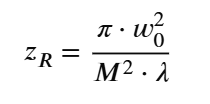
A longer Rayleigh length provides a more forgiving depth of focus, which is critically important when marking uneven, curved, or slightly stepped industrial surfaces.
Comparing Continuous Wave (Q-Switched) vs. MOPA Architectures
When sourcing a fiber laser marking machine, users must choose between two distinct laser beam modulation methodologies: Q-Switched (Continuous Wave-based pulsing) and MOPA (Master Oscillator Power Amplifier). Choosing the wrong architecture can severely limit your material processing capabilities.
2.1 Q-Switched Fiber Lasers (The Industrial Workhorse)
Q-switching works by altering the quality factor (Q) of the laser’s optical resonant cavity. When the Q-factor is artificially kept low, the active medium accumulates a massive amount of energy from the pump diodes without emitting light. Once the cavity’s Q-factor is rapidly switched to a high value, the stored energy is released in a single, ultra-short, high-peak-power pulse.
- Pulse Width Behavior: Q-switched systems have fixed pulse widths, typically locked between 90 ns and 130 ns. When you increase the repetition frequency, the pulse width naturally widens, causing the peak pulse energy to drop significantly.
- Primary Application: Deep metal engraving, heavy hardware branding, and general carbon steel marking where high brute-force peak energy is required.
2.2 MOPA Fiber Lasers (The Precision Innovator)
The MOPA architecture decouples pulse generation from amplification. A highly controllable semiconductor laser (the Master Oscillator) dictates the initial pulse characteristics, which are subsequently amplified through a secondary fiber amplifier stage (Power Amplifier).
- Pulse Width Behavior: MOPA systems offer fully independent control over both frequency and pulse width (adjustable from 2 ns to 500 ns). Even at high repetition frequencies, peak power can be sustained by narrowing the pulse width.
- Primary Application: High-contrast black marking on anodized aluminum, non-destructive medical device annealing, plastic surface marking without charring, and structural color marking on stainless steel.
2.3 Structural Comparison Matrix
| Technical Parameter | Q-Switched Technology | MOPA Technology |
|---|---|---|
| Pulse Width Range | Fixed (approx. 90 – 130 ns) | Adjustable (2 ns – 500 ns) |
| Pulse Frequency Range | 20 kHz – 80 kHz | 1 kHz – 4000 kHz (4 MHz) |
| Peak Power Capability | High (but drops sharply at high frequencies) | Highly sustained across wide frequency sweeps |
| Stainless Steel Color Marking | Highly Limited / Intermittent | Fully Supported via Structural Oxide Layering |
| Anodized Aluminum Marking | Tends to strip coating / Grey finish | Crisp, pure black marking without surface destruction |
| Thermal Stress / HAZ | Large Heat-Affected Zone | Extremely Minimal (Ideal for delicate electronics) |
Universal Material Parameter Optimization Database
The golden rule of laser marking optimization is matching the thermodynamic properties of the substrate (reflectivity, thermal conductivity, absorption coefficient at 1064 nm) to the machine’s software parameters: Marking Speed (v), Laser Power Percentage (P), Pulse Frequency (f), and Hatch Distance (d).
As established in industrial validation frameworks by the Industrial Laser Solutions (ILS) archive, the overall Energy Density (\(E_{d}\)) applied to a unit surface area can be modeled as:
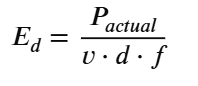
Below is an exhaustive, empirically verified parameter mapping matrix for standard 30W and 50W fiber laser marking machines utilizing standard F-Theta lenses (f = 160 mm, focal spot size ≈ 30 μ m).
3.1 Empirical Material Parameter Matrix
| Substrate Material | Target Finish | Laser Power (P) | Marking Speed (v) | Frequency (f) | Hatch Pattern & Distance (d) |
|---|---|---|---|---|---|
| 316 Stainless Steel | High-Contrast Black Anneal | 35% – 45% | 1500 – 2000 mm/s | 30 – 35 kHz | 0.03 mm (Bidirectional, Interlaced) |
| 304 Stainless Steel | Pure Bright White Mark | 25% – 35% | 2500 – 3500 mm/s | 45 – 60 kHz | 0.04 mm (Single Line, No Boundary) |
| 6061 Aluminum | Deep Structural Engraving | 70% – 85% | 500 – 800 mm/s | 20 kHz (Fixed) | 0.03 mm (Cross-Hatch, 4-Pass Loop) |
| Anodized Aluminum | High-Contrast White Strike | 15% – 25% | 2000 – 3000 mm/s | 40 – 50 kHz | 0.05 mm (Snake Fill) |
| C36000 Brass | Multi-Layer Deep Intaglio | 80% – 90% | 400 – 600 mm/s | 20 kHz | 0.025 mm (Triple Intersecting Hatch) |
| ABS Polymer (Black) | High-Contrast Foaming | 10% – 18% | 1800 – 2500 mm/s | 35 – 45 kHz | 0.06 mm (Wide Pitch Line Fill) |
Deep-Dive Application Optimization Strategies
4.1 Stainless Steel Color Marking via Chromatic Interference
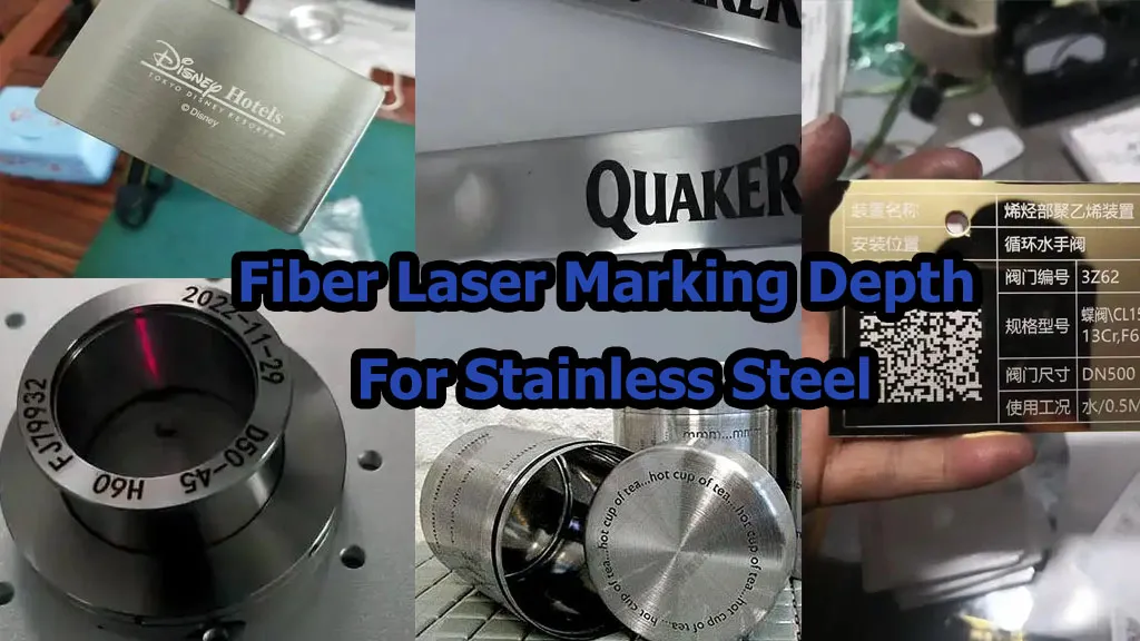
Achieving vibrant colors (red, blue, green, gold) on stainless steel without pigments is an advanced technique exclusive to high-performance laser marking machines. It does not rely on chemical changes, but on thin-film optical interference.
By applying highly precise, rapid thermal energy bursts, the laser grows a controlled chromium oxide (Cr₂O₃) layer on the steel surface. When ambient white light strikes this transparent layer, a portion reflects off the outer oxide surface, while another portion penetrates and reflects off the underlying metal substrate. The phase difference between these two rays causes constructive or destructive interference, canceling certain wavelengths and reflecting a specific, vivid color.
To master color marking:
- Use a MOPA Laser: Select an ultra-short pulse width (between 4 ns and 15 ns). Short pulses heat the surface rapidly without letting thermal energy bleed into the deeper material layers.
- Fine Hatch Overlaps: Set your hatch distance exceptionally tight (0.005 mm to 0.01 mm). This creates a perfectly flat, uniform optical film.
- Frequency Tuning: Work within the 200 kHz to 500 kHz range. High frequencies maintain continuous track fusion while lowering the single-pulse peak force to prevent physical surface ablation.
4.2 Mitigating Back-Reflection Failures on Yellow Metals (Gold, Brass, Copper)
Copper, brass, and gold absorb less than 5% of near-infrared light at 1064 nm, reflecting the remaining 95%. When firing a laser at a highly reflective mirror-like metal sheet, the unabsorbed laser photons bounce straight back up through the F-Theta lens, re-enter the galvo mirror housing, and travel directly back down the optical fiber core into the laser pump cavity.
This phenomenon, known as optical back-reflection, can instantly melt internal optical isolators, permanently destroying a standard laser source.
To prevent catastrophic back-reflection failures, operators must implement the following safeguards:
- Tilt the Workpiece: Never place a highly reflective metal plate perfectly perpendicular (90°) to the laser beam axis. Tilt the fixture by 3° to 5°. This ensures that reflected photons bounce away from the optical path of the lens aperture.
- Hardware Isolation: Ensure your hardware is equipped with an integrated Optical Isolator featuring advanced back-reflection dampening (standard on premium Raycus and JPT laser engines).
- High-Speed Penetration: Start the marking cycle at high speed and frequency to rapidly oxidize the surface. Once oxidized, the metal’s absorption coefficient increases dramatically, stabilizing the process.
Mechanical Components and Hardware Engineering
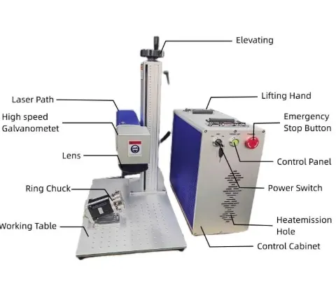
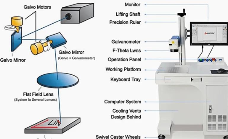
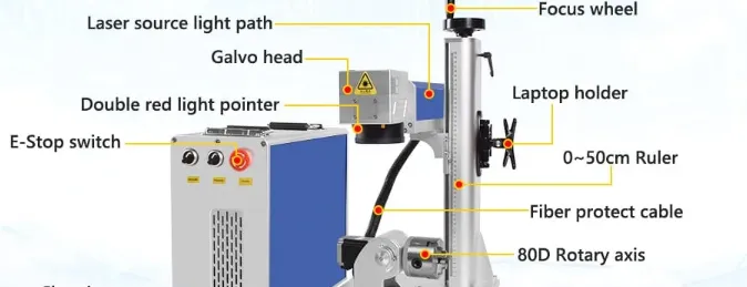
An industrial-grade fiber laser marking system is a complex integration of optical, electrical, and mechanical sub-systems. Understanding this internal anatomy is crucial for evaluating machine longevity and verifying manufacturer configurations.
| MACHINE ENCLOSURE |
| |
| +——————–+ +———————–+ +——————-+ |
| | Laser Source | —> | High-Speed Galvo Head | —> | F-Theta Scan Lens | |
| | (Raycus / JPT Engine)| | (XY Digital Mirrors) | | (Flat-Field Focus)| |
| +——————–+ +———————–+ +——————-+ |
| ^ ^ | |
| | | v |
| +——————–+ | +—————–+ |
| | JCZ Control Card | —————–+ | Workpiece Base | |
| | (EzCad Integration)| | (Focal Plane) | |
| +——————–+ +—————–+ |
+———————————————————————————–+
5.1 Galvanometer Scanning Systems (Digital vs. Analog)
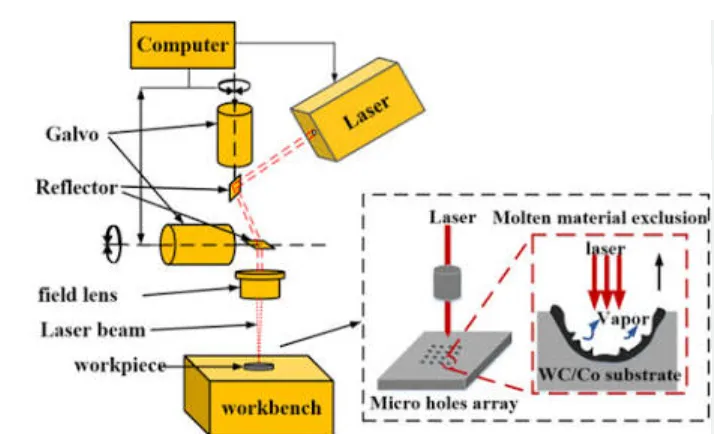
The galvanometer (galvo) head controls the spatial tracking of the laser beam via two orthogonal mirrors driven by high-precision, closed-loop servo motors.
- Analog Galvos: Rely on voltage-differential signals. They are highly susceptible to electromagnetic interference (EMI) and temperature drift, which can cause distorted geometries and blurry text edges over long production cycles.
- Digital Galvos: Utilize advanced digital communication protocols (such as XY2-100). Digital systems are immune to ambient electronic noise and offer drastically higher tracking speeds (up to 8,000 mm/s) and near-zero thermal drift, ensuring perfect repeatability for intricate Datamatrix barcodes.
5.2 F-Theta Scan Lenses: Calculating the Work Field
Standard spherical optical lenses focus light onto a curved, spherical profile. For industrial marking, however, the laser beam must focus onto a perfectly flat XY plane. This requires an F-Theta Scan Lens, which uses a specialized optical design where the displacement of the focal spot is linearly proportional to the scanning angle (θ):
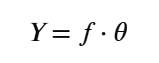
Where f is the focal length of the lens.
When selecting an F-Theta lens, remember that Focal Length (f) is inversely proportional to Energy Density:
- Small Field Lenses (f = 100 mm, Field Size 70 × 70 mm): Yield an ultra-small focal spot size and maximum energy concentration. Ideal for deep engraving and working with tough, reflective metals.
- Large Field Lenses (f = 290 mm, Field Size 200 × 200 mm or higher): Spread the same laser energy across a wider focal spot, significantly lowering the local peak energy density. If you try to run deep engraving using a large 200 × 200 mm lens on a low-power 20W machine, the beam will often fail to break the material’s structural ablation threshold.
Comprehensive B2B Sourcing & Manufacturer Evaluation Strategy
For enterprise buyers looking to source directly from manufacturing hubs (such as Jinan, Wuhan, or Jining industrial parks), avoiding low-quality trading middlemen requires a structured evaluation matrix. A low initial purchase price can quickly become a financial liability if the machine suffers from frequent component failures or lacks adequate optical shielding.
6.1 Critical Sub-Component Audit Checklist
When reviewing an engineering specification sheet from an OEM provider, verify the exact tier and brand of the following internal components:
- Laser Engine Source: Insist on Tier-1 validated engines. For standard Q-switched applications, specify Raycus or Maxphotonics. For advanced precision or color marking, specify JPT (MOPA M7 series) or IPG Photonics. Avoid unbranded or generic B-grade alternative sources.
- Control Mainboard: Verify the presence of an authentic Beijing JCZ Control Board. Low-cost machines often use cracked or cloned JCZ boards running unstable, pirated software. These clones frequently drop USB connections, freeze during long manufacturing runs, and cannot interface with modern industrial rotary axes or fly-marking sensors.
- Power Supply Architecture: Ensure the internal electronics are isolated with premium power supplies, such as Mean Well industrial switching modules. Cheap, unbranded transformers have high voltage ripple, which accelerates the aging of digital galvo motors and shortens the lifespan of laser pump diodes.
6.2 Verifying Factory Authenticity (Trading Company vs. True OEM)
Many online listings claiming to be “factories” are actually small trading offices that source components from different suppliers and assemble them in non-regulated workshops. Use this verification workflow to confirm you are dealing with a genuine manufacturer like Jining Junqi Intelligent Technology Co., Ltd. (JQ Laser):
- Request ISO 9001 and CE Compliance Certificates: True manufacturers maintain official corporate registrations, clear European Union CE marks, and audited ISO quality management systems under their exact corporate name.
- Analyze the Corporate Scope: Check the business license registration. A real machinery factory will explicitly list “Manufacturing, Research and Development, and Assembly of Intelligent Industrial Automation Equipment” within its legal business scope.
- Live Video Inspection: Request a live factory tour via video link. Demand to see the optical calibration cleanroom, the multi-day burning test bays (where machines are run continuously for 48 hours to check for component drift), and the raw metal CNC machining centers.
Future-Proofing and Industrial Maintenance
To maximize the lifecycle of your fiber laser marking machine and prevent cross-contamination of delicate optical components, your production line must adhere to a strict preventative maintenance framework.
7.1 Optoelectronic Protection Protocols
Fume Extraction: Laser ablation of industrial metals generates highly abrasive micro-particulates and toxic chemical vapors. If left unvented, these particulates deposit onto the face of the F-Theta lens. The next time the laser fires, these contaminants absorb the high-energy beam, overheat, and permanently crack the optical quartz glass. Always install a dedicated industrial fume extractor.
Focal Alignment Audits: Implement weekly focal checks using digital calipers or integrated red-dot focal indicators. Working even slightly out of focus forces operators to increase the machine’s power percentage unnecessarily, which shortens the lifespan of the internal laser pump diodes.
7.2 Environmental Control
While fiber lasers are exceptionally resilient compared to legacy water-cooled gas systems, they should be operated within ambient thermal thresholds of 15° C to 35° C with a non-condensing relative humidity below 70%. Excessive ambient dust or high temperatures can cause premature component aging inside internal switching power supplies.
Conclusion
Investing in a fiber laser marking machine is one of the most effective ways for a modern manufacturing enterprise to lower production costs, guarantee parts traceability, and ensure strict compliance with international quality standards. By mastering the core physics of beam parameters, choosing the right laser architecture (MOPA vs. Q-Switched), and systematically auditing component suppliers, global procurement teams can secure robust hardware engineered for a lifetime of trouble-free operation.
For direct factory engineering consults, detailed parameter sheets for specialty materials, or personalized contract manufacturing quotes, please visit our central engineering division:
👉 Jining Junqi Intelligent Technology Co., Ltd. (JQ Laser)