Author: LEO, Sales Engineer at JQ Laser
Technical Review: JQ Laser Manufacturing & Quality Control Team
Company: Jining Junqi Intelligent Technology Co., Ltd.
Last Updated: November 2026
Category: Laser Marking Applications / Metal Marking Technology
Introduction: Can You Permanently Laser Mark Serial Numbers on Tool Steel?
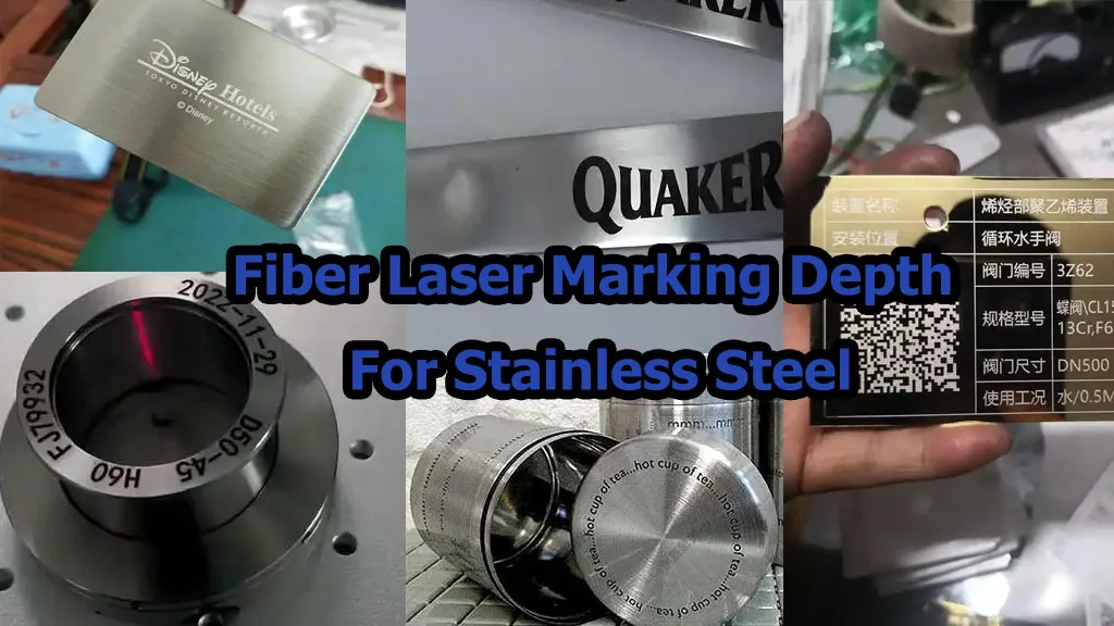
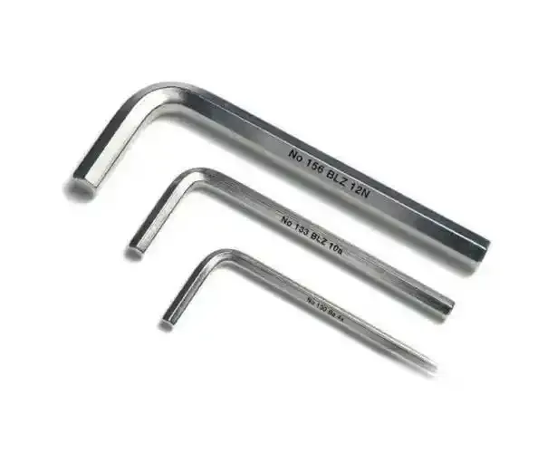
Yes. A 1064 nm fiber laser marking machine can mark permanent serial numbers on many tool steels, including hardened D2, H13, SKD11, and M2 components. However, the result depends on more than laser power. Steel grade, heat treatment, surface finish, hardness, coatings, and the required marking depth all affect the process. A shallow black mark may be suitable for identification, while a tool exposed to repeated grinding, abrasion, or high-temperature service may need a deeper engraved mark. Before production, test the actual heat-treated workpiece, verify code readability, and check whether marking affects the functional surface.
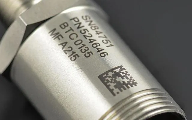
Table of Contents
1. Why Is Laser Marking Tool Steel More Complicated Than Marking Ordinary Steel?
If you manufacture punches, dies, cutting tools, molds, or precision tooling, you probably already know the problem.
You need a permanent serial number, but you cannot simply engrave anywhere on the component.
A marking that looks good immediately after processing may become difficult to read after:
- Heat treatment.
- Grinding and polishing.
- Repeated tool use.
- Cleaning with industrial chemicals.
- Surface coating.
- High-temperature operation.
- Contact with other metal components.
We often recommend that buyers answer one question before selecting a laser:
At what stage of your manufacturing process will the serial number be applied?
This makes a major difference.
For example:
- A D2 punch marked before final grinding may lose part or all of its identification.
- An H13 die insert marked after heat treatment needs a process that respects its hardened condition.
- An M2 cutting tool may need identification in a location that does not interfere with its cutting edge.
- A coated mold component may need marking before coating, after coating, or in a specifically approved identification area.
The laser should be selected around the complete manufacturing process, not just the material name.
Common tool steels and their applications
| Tool steel | Common material designation | Typical applications | Main marking concern |
|---|---|---|---|
| D2 | AISI D2 / 1.2379 / SKD11 | Cold-work dies, punches, cutting tools | High hardness and wear resistance |
| H13 | AISI H13 / 1.2344 / SKD61 | Hot-work dies, extrusion tooling | Elevated service temperature |
| M2 | AISI M2 / 1.3343 | High-speed cutting tools | Hardness and cutting-edge protection |
| O1 | AISI O1 / 1.2510 | Precision punches, dies, cutting tools | Heat-treated surface condition |
| A2 | AISI A2 / 1.2363 | Cold-work tooling | Surface finish and wear |
| S7 | AISI S7 | Impact-resistant tools | Impact loading and crack sensitivity |
| P20 | AISI P20 / 1.2311 | Plastic injection molds | Surface finish and mold appearance |
| SKD61 | JIS SKD61 | Hot-work dies and tooling | Heat exposure and surface condition |
These are common commercial designations and approximate cross-reference examples, not proof that every grade is chemically identical. Always confirm the actual material certificate and specification. ASTM A681-24, for example, covers chemical, mechanical, and physical requirements for wrought alloy tool steels, including hardness and decarburization considerations.
2. The Actual Machine Configuration: What Do You Need to Mark Tool Steel?
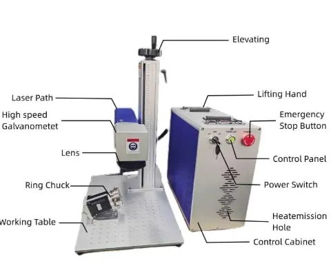
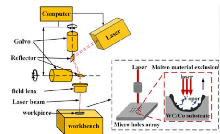
A standard pulsed fiber laser is usually the first technology we would evaluate for tool steel identification.
However, the machine configuration should match the desired mark.
2.1 Reference JQ Laser fiber laser specifications
| Parameter | JQ Laser reference configuration |
|---|---|
| Laser type | Pulsed fiber laser |
| Laser wavelength | 1064 nm |
| Available laser power | 20W / 30W / 50W / 100W |
| Laser source options | Raycus / JPT / MAX, subject to configuration |
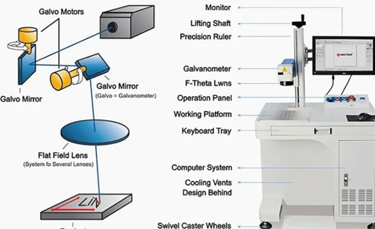
| Galvanometer scanner | Industrial galvo scanning system |
| Standard marking field | 110 × 110 mm |
| Optional marking fields | 150 × 150 / 175 × 175 / 200 × 200 / 300 × 300 mm |
| Reference maximum scanning speed | Up to approximately 7,000 mm/s |
| Cooling | Air cooling for common configurations |
| Control system | JCZ / BJJCZ-compatible configuration |
| Marking software | EZCAD2, subject to configuration |
| Electrical supply | 110V / 220V, 50/60Hz according to destination requirements |
These are reference equipment specifications. The final configuration must be confirmed in the quotation.
2.2 Which power should you choose?
| Power | Typical use on tool steel | Practical consideration |
|---|---|---|
| 20W | Serial numbers, logos, shallow surface marking | Suitable starting point for identification trials |
| 30W | Regular identification and production marking | More processing capacity for many applications |
| 50W | Deeper engraving and more demanding production | Useful when material removal or cycle time is important |
| 100W | Industrial engraving and high-volume applications | Requires careful thermal and process evaluation |
One important point: a 50W machine does not automatically produce a better mark than a 20W machine.
For example, if your D2 punch only needs a clear 6-digit serial number, a properly configured 20W or 30W machine may be sufficient.
If the same punch requires a deeper engraved identification that must survive repeated cleaning and handling, a higher-power machine may be worth testing.
The final decision should be based on measured engraving depth, readability, cycle time, and surface integrity.
2.3 What about MOPA fiber lasers?
MOPA fiber lasers, such as configurations using JPT M7 sources, allow pulse-width adjustment.
This can provide additional flexibility when evaluating:
- Dark surface marking.
- Fine identification.
- Different oxide appearances.
- Controlled heat input.
- Marking on selected coated or treated surfaces.
However, MOPA does not guarantee a lower heat-affected zone or better durability in every application. The result depends on pulse characteristics, energy input, overlap, focus, and the steel itself.
For simple serial numbers on conventional tool steel, a standard pulsed fiber laser is often the sensible first option.
3. Eight Material Limits You Must Check Before Laser Marking Tool Steel
This is the most important section of the guide.
A supplier can show you a perfect sample on a piece of polished steel, but that does not prove the same settings will work on your hardened die or production punch.
We recommend completing the following eight material checks before confirming the machine configuration.
Check 1: Confirm the Actual Steel Grade and Material Chemistry
Applicable conditions
- D2 / SKD11 cold-work tooling.
- H13 / SKD61 hot-work dies.
- M2 high-speed steel.
- A2, O1, S7, and other alloy tool steels.
- Mixed-material production batches.
Why it matters
Two workpieces may both be described as tool steel, but their chemical composition and metallurgical condition can be very different.
Alloying elements, carbon content, carbide distribution, and non-metallic inclusions can influence the way the surface responds to laser energy.
For example, a marking recipe developed on one D2 batch should not automatically be copied to a different supplier’s D2 material without checking the result.
Evidence and test method
- Obtain the material grade from the drawing or purchase specification.
- Request the material certificate when available.
- Record the heat or batch number.
- Confirm whether the material has been annealed, hardened, or surface treated.
- Test a representative sample from the actual production batch.
For unidentified materials, handheld XRF may help screen certain alloying elements, but it does not reliably determine carbon content. Use an appropriate laboratory method if the exact grade is critical.
Limitations
A material name alone is insufficient. AISI D2, DIN 1.2379, and JIS SKD11 are commonly cross-referenced, but the actual supply specification and chemistry still need verification.
Check 2: Verify Hardness and Heat Treatment
Applicable conditions
- Hardened D2 punches.
- Heat-treated H13 die inserts.
- M2 cutting tools.
- Quenched and tempered precision tooling.
Why it matters
The same steel can behave differently before and after heat treatment.
A laser mark on annealed steel is not automatically a suitable reference for hardened steel.
The hardness itself is not the only concern. The heat-treatment history, surface microstructure, residual stress, and any subsequent grinding operation also matter.
Evidence and test method
- Check the heat-treatment report.
- Record the specified hardness range.
- Measure hardness using the appropriate method, such as Rockwell C for suitable hardened components.
- Record the measurement location.
- Test laser marking on the final heat-treated condition.
- Compare the mark before and after any planned finishing operation.
Practical recommendation
For a D2 die insert, if the serial number must remain visible after final grinding, test the marking after grinding rather than using an annealed blank as your only sample.
Limitations
Do not assume that laser marking will leave hardness unchanged simply because the mark is shallow.
If the component has strict hardness, fatigue, or surface-integrity requirements, additional metallurgical testing may be necessary.
Check 3: Check Surface Finish, Oxide, and Decarburization
Applicable conditions
- Ground tool steel.
- Polished mold inserts.
- Black oxide surfaces.
- Machined tooling.
- Heat-treated components with scale.
Why it matters
The surface condition determines how the laser interacts with the workpiece.
A polished D2 component may produce a different visual contrast from a rough-ground one.
Oxide scale can also make the marking inconsistent. In some cases, the laser may mainly remove the existing surface layer rather than produce a controlled mark in the base steel.
Decarburized surfaces can behave differently from the underlying material.
Evidence and test method
- Photograph the workpiece before marking.
- Record the surface preparation method.
- Measure roughness if it is part of the drawing requirement.
- Compare marked areas on polished, ground, and as-treated samples.
- Inspect the mark under consistent lighting.
- Check whether cleaning or light abrasion changes readability.
Practical recommendation
If the production batch contains both polished and ground tooling, do not approve one marking recipe for both conditions without testing.
Limitations
Visual appearance alone cannot confirm surface integrity or metallurgical condition.
Check 4: Identify Coatings, Nitriding, and Surface Treatments
Applicable conditions
- TiN-coated punches.
- TiAlN-coated cutting tools.
- CrN-coated tooling.
- Nitrided H13 dies.
- Black oxide and other conversion-coated components.
Why it matters
A coated tool is not simply bare steel.
The laser may remove the coating, discolor it, expose the substrate, or produce a mark that looks different from the customer’s intended appearance.
For example, a serial number marked on a TiN-coated punch may become highly visible because the laser removes part of the coating.
But this may not be acceptable if the coating must remain intact.
Evidence and test method
- Confirm the coating type.
- Obtain the coating thickness or treatment information where available.
- Define whether coating removal is allowed.
- Mark a sample with the actual production coating.
- Inspect coating edges under magnification.
- Check for peeling, cracking, discoloration, or unwanted exposed substrate.
Practical recommendation
For a coated punch, agree on one of these requirements before testing:
- Mark through the coating to expose the substrate.
- Produce a visible mark while preserving the coating.
- Mark an uncoated identification area before coating.
- Use a separate identification plate or approved marking location.
Limitations
A laser mark that removes a functional coating may reduce local wear or corrosion protection. Do not mark a working surface without approval from the tool designer or coating supplier.
Check 5: Check Workpiece Geometry and Marking Position
Applicable conditions
- Small punches.
- Cylindrical cutting tools.
- Mold inserts.
- Deep cavities.
- Curved tooling surfaces.
- Components with narrow identification areas.
Why it matters
A standard flat-field marking machine does not automatically produce consistent marks on every curved or recessed surface.
If the workpiece is not at the correct focal distance, the laser spot and marking quality can change.
A serial number placed too close to a cutting edge may also interfere with the tool’s function.
Evidence and test method
- Measure the workpiece dimensions.
- Identify the marking location on the drawing.
- Check the focal distance.
- Test the full identification layout.
- Verify the mark at different positions.
- Evaluate a rotary axis or custom fixture for cylindrical parts.
Practical recommendation
For a cylindrical tool shank, a rotary attachment can help maintain consistent positioning around the circumference.
For irregular die inserts, a dedicated fixture may be more useful than buying a higher-power laser.
Limitations
A standard 110 × 110 mm marking field is a flat-field specification, not a guarantee that a 110 mm curved or recessed surface can be marked uniformly.
Check 6: Decide Whether You Need Surface Marking or Actual Engraving
Applicable conditions
- Permanent serial numbers.
- Tool identification.
- Asset tracking.
- Deep identification on reusable tooling.
- Marks exposed to repeated abrasion.
Why it matters
This is where many purchasing misunderstandings happen.
A black laser mark and an engraved serial number are not the same thing.
A surface mark can provide strong visual contrast without removing much material.
An engraved mark removes material and creates measurable depth.
If the workpiece is repeatedly ground, polished, or abraded, a shallow surface mark may disappear.
Evidence and test method
For surface marking:
- Check contrast.
- Check character shape.
- Verify code readability.
- Test resistance to the actual cleaning process.
For engraved marking:
- Measure depth using a suitable profilometer or optical measurement system.
- Check character edges.
- Inspect for burrs and unwanted material redeposition.
- Compare engraving depth with the customer’s drawing requirement.
Practical recommendation
If a serial number must survive routine cleaning and handling, a well-developed surface mark may be sufficient.
If it must survive substantial material removal or mechanical abrasion, specify a minimum engraving depth and validate it with an actual wear test.
Limitations
No laser mark should be described as permanent under all conditions. Permanence must be defined against the expected service life and subsequent manufacturing or maintenance operations.
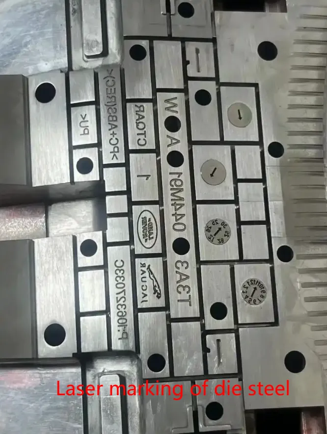
Check 7: Evaluate Heat Input and Possible Surface Damage
Applicable conditions
- High-hardness D2 tooling.
- Precision mold inserts.
- Fatigue-sensitive components.
- Components operating under cyclic loads.
- Tools with strict surface-integrity requirements.
Why it matters
Laser marking is a localized thermal process.
Even when the visible mark is small, the material below or around the marked area may experience thermal changes.
Depending on the material and laser parameters, potential concerns include:
- Local oxidation.
- Recast material.
- Microcracking.
- Changes in near-surface microstructure.
- Local hardness variation.
- Damage to coatings.
This is particularly important for components where surface fatigue or crack initiation could affect service life.
Research on laser-marked steels shows that process heat input and pulse characteristics can influence the affected surface. Studies on stainless steels are not direct proof of the behavior of D2 or H13, but they demonstrate why surface integrity should be tested rather than assumed.
Evidence and test method
For critical tooling, consider:
- Visual inspection under magnification.
- Cross-sectional metallographic examination.
- Microhardness testing near the marked area.
- Surface roughness measurement.
- Dye penetrant or another suitable crack inspection method, where appropriate.
- Comparison against an unmarked control sample.
Practical recommendation
Start with the lowest heat input that produces the required mark quality, then increase the process intensity only when necessary.
Do not solve every contrast problem by repeatedly increasing laser power.
Limitations
A visual inspection cannot prove the absence of a heat-affected zone or microcracks. For critical parts, agree on a metallurgical acceptance method with the customer.
Check 8: Verify Serial Number Readability and Service-Life Durability
Applicable conditions
- Automotive tooling.
- Aerospace tooling.
- Mold and die identification.
- Industrial maintenance records.
- QR code and Data Matrix traceability.
Why it matters
A serial number is useful only if it remains readable when the customer needs it.
A mark may look clear on a computer screen but fail when scanned on the actual component.
Reflective surfaces, small characters, shallow marks, dirt, oil, and changing illumination can all affect reading performance.
Evidence and test method
- Inspect character height and line width.
- Verify the serial number against the production database.
- Scan the mark using the intended reader.
- Repeat the scan under realistic lighting.
- Clean the workpiece using the actual production cleaning process.
- Conduct abrasion or service-condition tests where necessary.
- Record the result before and after testing.
For Data Matrix identification on metallic parts, SAE AS9132B defines quality and technical requirements for part marking in aerospace applications and includes laser marking among the covered processes. It should be used when the customer invokes that requirement, not assumed to apply to every industrial serial number.
Practical recommendation
If your customer requires a machine-readable code, request an actual code verification result rather than accepting a photograph of a good-looking mark.
Limitations
A readable code immediately after marking does not establish long-term durability. The acceptance test must represent the actual cleaning, wear, and service environment.
4. Tool Steel Material Validation Checklist: Quick Comparison
After completing the eight checks, use this table to decide which tests are most important for your particular workpiece.
| Material or condition | Main risk | First test to perform | Additional verification |
|---|---|---|---|
| Hardened D2 / SKD11 | Heat input and surface damage | Mark actual hardened sample | Microhardness and microscopy if critical |
| H13 / SKD61 | High-temperature service | Mark after final heat treatment | Service-temperature evaluation |
| M2 high-speed steel | Cutting-edge interference | Mark a non-functional area | Edge inspection and wear evaluation |
| Ground A2 / O1 | Surface finish variation | Compare different surface finishes | Contrast and repeatability |
| TiN / TiAlN coating | Coating removal or damage | Coated-sample test | Magnified coating-edge inspection |
| Nitrided tooling | Modification of hardened surface | Test the actual nitrided condition | Cross-section or hardness check |
| Polished mold inserts | Low contrast and cosmetic defects | Fine-marking trial | Surface roughness and appearance |
| Abrasion-exposed tooling | Loss of readability | Define depth and abrasion test | Re-read after wear test |
Which marking method should you choose?
| Requirement | Standard pulsed fiber | MOPA fiber | Dot peen / mechanical marking |
|---|---|---|---|
| Basic serial numbers | Suitable starting option | Suitable | Suitable |
| High-contrast surface marks | Requires parameter testing | More pulse control | Different mark appearance |
| Controlled dark marking | Material-dependent | More process flexibility | Not intended for oxide color marking |
| Deep engraving | Suitable with appropriate power and passes | Suitable with appropriate configuration | Produces mechanical indentation |
| Coating removal | Possible, test carefully | Possible, test carefully | Depends on coating and tooling |
| Curved workpieces | Rotary or fixture may be needed | Rotary or fixture may be needed | Depends on equipment |
| Marks exposed to heavy abrasion | Depth validation required | Depth validation required | Indentation may be considered |
| Fine, detailed identification | Suitable | Suitable | Limited by mechanical marking resolution |
Our recommendation: For most tool steel serial-number projects, evaluate a standard pulsed fiber laser first. Consider MOPA when pulse flexibility or surface appearance is important. If the mark must withstand severe mechanical wear or material removal, compare laser engraving with dot peen marking rather than assuming a shallow laser mark will be sufficient.
5. How We Test Tool Steel Samples Before Recommending a Machine
We do not recommend choosing a machine only from a photograph or a material name.
A proper test should use the customer’s real workpiece, preferably after all relevant heat treatment and surface finishing.
5.1 Sample information we need
| Information | Example |
|---|---|
| Material grade | D2 / SKD11 |
| Heat treatment | Quenched and tempered |
| Hardness | 58–60 HRC (customer-specified example) |
| Surface condition | Ground / polished |
| Coating | None / TiN / TiAlN / nitrided |
| Workpiece size | 80 × 30 × 15 mm |
| Marking content | JQ-2026-0001 |
| Marking area | 20 × 8 mm |
| Required appearance | Dark serial number |
| Required depth | Customer-defined |
| Daily quantity | 300 pieces |
| Service condition | Oil cleaning and repeated handling |
The 58–60 HRC value above is an example of information a customer might supply. It is not a guaranteed marking limit or a machine specification.
5.2 Our sample testing procedure
Step 1: Identify the material
We confirm the grade, surface condition, hardness, and treatment history.
Step 2: Confirm the required result
We ask whether the customer wants a dark mark, a light mark, a visible engraving, or a machine-readable serial code.
Step 3: Select the laser configuration
We assess whether a standard fiber laser or MOPA configuration is more appropriate.
Step 4: Develop a parameter test matrix
The technician adjusts the relevant process variables:
- Laser power.
- Frequency.
- Scanning speed.
- Pulse width, where available.
- Hatch spacing.
- Number of passes.
- Focus position.
Instead of changing several parameters randomly, we record each trial so that the relationship between settings and results can be evaluated.
Step 5: Inspect the samples
We check:
- Character clarity.
- Edge definition.
- Contrast.
- Marking depth.
- Surface damage.
- Repeatability.
- Code readability, where required.
Step 6: Validate the result
If the application is critical, we agree on additional hardness, microscopy, crack, or abrasion testing.
Step 7: Confirm the quotation
Only after the sample result is reviewed do we finalize the recommended laser power, lens, fixture, and machine configuration.
5.3 Example of a sample test record
The following is a recommended documentation format, not a claim of an already completed customer test.
| Trial ID | Laser configuration | Surface condition | Test objective | Result to record |
|---|---|---|---|---|
| TS-D2-01 | 20W fiber | Hardened and ground | Surface contrast | Contrast and clarity |
| TS-D2-02 | 30W fiber | Hardened and ground | Production marking | Cycle time and readability |
| TS-D2-03 | 50W fiber | Hardened and ground | Engraving capability | Measured depth and surface condition |
| TS-D2-04 | MOPA fiber | Hardened and polished | Dark mark development | Color consistency and surface integrity |
| TS-D2-05 | Selected configuration | Actual production part | Final verification | Acceptance result |
Every sample should have a traceable identification record containing:
- Customer or project reference.
- Workpiece material and batch.
- Sample date.
- Machine and laser source configuration.
- Lens and marking field.
- Parameter file or revision.
- Inspection method.
- Photograph of the result.
- Customer approval status.
This record makes it easier to reproduce the same process when the customer places a production order.
6. Real Applications: Where Do Permanent Tool Steel Serial Numbers Matter?
Application 1: D2 Punches and Cold-Work Dies
A stamping-tool manufacturer may need to identify individual punches with a unique serial number.
The identification must remain visible during maintenance and tool replacement.
Recommended approach:
- Mark after final heat treatment and grinding, if that is the approved production stage.
- Avoid cutting edges and high-stress areas.
- Test contrast and surface integrity.
- Use a dedicated fixture to maintain repeatable positioning.
A 20W or 30W fiber laser can be evaluated for standard identification. Higher power should be considered only if the required depth or cycle time justifies it.
Application 2: H13 Hot-Work Die Inserts
H13 is widely used in hot-work tooling.
A die insert may be exposed to elevated temperature, thermal cycling, and mechanical loading.
The key question is not simply whether the laser can create a dark serial number.
It is whether the identification remains readable under the actual service conditions and whether the marking affects the approved surface condition.
Recommended approach:
- Confirm the final heat-treatment state.
- Choose an approved non-functional identification area.
- Compare surface marking and shallow engraving.
- Test the sample against the actual service-temperature and cleaning requirements.
Do not assume that a mark tested at room temperature will remain readable after repeated thermal cycles.
Application 3: M2 High-Speed Cutting Tools
Drills, milling cutters, and other M2 tools often have narrow surfaces and functional cutting edges.
A serial number may need to be placed on the shank rather than the cutting portion.
Recommended approach:
- Use a fixture that keeps the tool aligned.
- Confirm the focal position.
- Test small characters.
- Check that the marking does not interfere with tool geometry.
- Consider rotary marking for cylindrical shanks.
Application 4: P20 Plastic Mold Inserts
A mold manufacturer may need to identify mold cavities, insert numbers, and maintenance records.
P20 is frequently used in plastic mold applications.
The surface may be polished or textured, so the mark must not damage the cosmetic or functional mold surface.
Recommended approach:
- Mark a designated identification zone.
- Test on the actual polished condition.
- Check for visible discoloration and unwanted texture changes.
- Keep the mark away from the mold cavity’s critical forming surface.
Application 5: Tooling for Automotive Production
Automotive factories often require tooling identification to support maintenance, replacement, and production records.
The serial number may be associated with a tool number, production line, maintenance history, and inspection record.
For this type of application, a machine-readable Data Matrix code can be considered.
The code should be verified with the actual reader and acceptance criteria required by the customer.
7. What Makes a Serial Number Truly Permanent?
This is a question worth discussing before you order a machine.
In practical production, permanent does not mean indestructible.
It means the mark remains readable through the operations and service conditions specified by the customer.
A serial number can be lost through:
- Grinding away the marked surface.
- Polishing.
- Severe abrasion.
- Coating over the identification.
- Corrosion or aggressive chemical cleaning.
- Excessive heat exposure.
- Mechanical damage.
Define permanence with measurable requirements
| Requirement | Suggested acceptance method |
|---|---|
| Visual readability | Compare against an approved reference sample |
| Engraving depth | Measure with a suitable depth-measurement instrument |
| Character dimensions | Optical measurement |
| QR / Data Matrix readability | Verify using the specified code reader |
| Abrasion resistance | Customer-defined abrasion test |
| Cleaning resistance | Actual cleaning chemical and procedure |
| Heat resistance | Representative thermal exposure |
| Surface integrity | Microscopy, hardness or crack inspection as applicable |
For aerospace and other demanding applications, do not rely on a general statement that a code is readable.
SAE AS9132B is relevant when a customer specifies Data Matrix quality requirements for metallic parts marking. The standard addresses the requirements for electronic readability and includes laser marking within its scope.
The exact standard revision, customer drawing, and acceptance requirements should be confirmed before the project begins.
8. What Should You Ask a Fiber Laser Marking Machine Supplier Before Purchasing?
If you are buying a machine for tool steel production, the supplier should understand more than the material name.
Here are the questions we recommend asking.
| Question | What a reliable supplier should provide |
|---|---|
| Can you mark my hardened D2 or H13 sample? | Actual sample test |
| Which laser source is included? | Brand and model |
| What is the actual marking depth? | Measured test result |
| Can the serial number survive cleaning? | Cleaning test evidence |
| Can you mark coated tool steel? | Coated-sample evaluation |
| Can you provide repeatable results? | Parameter file and sample record |
| Can you support small batches? | Standard machine purchasing terms |
| Can you customize the machine? | OEM and configuration options |
| What is the delivery time? | Confirmed production schedule |
| What spare parts are available? | Spare parts list and warranty terms |
8.1 Factory capability and manufacturing process
Jining Junqi Intelligent Technology Co., Ltd. operates under the JQ Laser brand in Qufu, Jining, Shandong, China.
Our manufacturing and assembly workflow covers:
- Preparation of laser sources and optical components.
- Mechanical assembly.
- Electrical installation.
- Galvanometer and lens configuration.
- Software installation.
- Laser operation and marking tests.
- Final inspection.
- Export packaging.
For tool steel applications, the most important part of the process is not simply assembling the machine.
It is selecting and verifying a configuration that produces the required result on the customer’s actual workpiece.
8.2 OEM and ODM customization
For distributors and industrial equipment buyers, we can discuss:
- Machine logo and nameplate customization.
- Selected machine appearance and color.
- Customized packaging.
- Different laser source configurations.
- 110V or 220V electrical configurations.
- Different marking fields.
- Rotary fixtures.
- Dedicated tooling fixtures.
- Customized automation solutions.
The available options depend on the project and machine configuration.
8.3 MOQ and lead time
We do not apply one universal MOQ or delivery time to every project.
For standard machines, individual and small-batch purchasing can be discussed.
OEM orders may require a different MOQ depending on branding, packaging, and customization.
Automatic systems may need additional time for fixture development, PLC integration, and sample validation.
Before confirming an order, request written confirmation of:
- Machine configuration.
- MOQ.
- Production lead time.
- Sample approval status.
- Inspection requirements.
- Packaging details.
- Shipping arrangement.
8.4 Quality inspection and spare parts
Before shipment, buyers should request evidence of:
- Laser source model.
- Galvanometer and lens configuration.
- Electrical system checks.
- Software operation.
- Marking test results.
- Accessories and packing list.
- Final machine photographs.
For long-term operation, discuss spare parts such as:
- F-theta lenses.
- Protective optical components, where applicable.
- Power supplies.
- Control cards.
- Galvanometer components.
- Foot switches.
- Exhaust equipment.
Warranty conditions and replacement arrangements should be confirmed in the quotation or purchase agreement.
8.5 Export support
For overseas buyers, we can discuss export packing, commercial invoices, packing lists, transport documentation, user manuals, and applicable technical or conformity documents.
Import requirements differ between countries. Confirm any required electrical, laser-safety, and conformity documentation before placing the order.
9. Frequently Asked Questions
1. Can a 20W fiber laser mark hardened D2 tool steel?
A 20W pulsed fiber laser can be evaluated for serial numbers and surface identification on hardened D2. Whether it meets the required contrast, depth, and production speed depends on the actual hardness, surface condition, and marking requirements. Test a representative hardened sample before purchasing.
2. What is the best laser power for marking SKD11 or D2?
For ordinary identification, 20W or 30W is a reasonable starting point. For deeper engraving or higher production demands, 50W or 100W may be considered. Actual sample results should determine the final choice.
3. Can a fiber laser engrave H13 after heat treatment?
Yes, H13 can be evaluated for laser marking or engraving after heat treatment. However, the process should be tested on the final hardened condition. For critical dies, inspect the marked area for surface damage and any unacceptable metallurgical changes.
4. Does laser marking change tool steel hardness?
It can potentially affect the near-surface material depending on heat input and processing conditions. A visual mark does not prove that the underlying material is unchanged. For critical tooling, use an appropriate microhardness test and metallographic inspection.
5. Can laser marking remove TiN or TiAlN coatings?
A fiber laser may remove or modify certain coatings, but the result depends on coating composition, thickness, and laser parameters. Test the actual coated component and confirm whether coating removal is permitted.
6. Is black laser marking more permanent than deep engraving?
Not necessarily. Black marking often provides good visual contrast, while deep engraving provides measurable material removal. If the component is exposed to grinding or abrasion, engraving depth may be more important than initial contrast.
7. Can serial numbers be marked on cylindrical tool shanks?
Yes. A rotary attachment or suitable fixture can help mark cylindrical surfaces. Workpiece diameter, curvature, focal position, and required marking length should be checked before selecting the system.
8. Can a laser mark survive repeated cleaning and industrial use?
It depends on the mark type and the actual cleaning or wear conditions. A sample should be tested using the same chemicals, temperatures, and abrasion conditions expected in production.
9. Can the machine mark Data Matrix codes on tool steel?
Yes. A fiber laser can produce Data Matrix codes on suitable tool steel surfaces. Code size, contrast, surface condition, and scanner performance must be verified. If the customer specifies SAE AS9132B or another code-quality requirement, use the applicable acceptance criteria.
10. Should I mark tool steel before or after heat treatment?
This depends on the manufacturing sequence. If subsequent grinding or polishing will remove the marked surface, marking before finishing may not be suitable. For many identification applications, marking after final heat treatment and surface finishing is worth evaluating.
11. Can JQ Laser test my own tool steel samples?
Yes. Send us the material grade, hardness, surface condition, photographs, and required serial number. Actual workpieces are recommended when marking depth, coating compatibility, or surface integrity is important.
12. What information do you need to recommend a machine?
We need the material grade, hardness, workpiece dimensions, surface treatment, serial number size, required marking depth, daily production volume, and destination country. If you are unsure about laser power, our team can help evaluate a suitable configuration.
10. Request a Tool Steel Laser Marking Sample Test
Are you manufacturing punches, dies, cutting tools, mold inserts, or other hardened steel components?
Before purchasing a laser marking machine, let us evaluate your actual workpiece.
We would rather test your D2, H13, SKD11, or M2 sample first than recommend a machine based only on a product photograph.
Send us these project details
| Project information | Example |
|---|---|
| Material | D2 / SKD11 / H13 / M2 |
| Hardness | 58–60 HRC |
| Surface condition | Ground / polished / coated |
| Workpiece dimensions | 80 × 30 × 15 mm |
| Serial number | JQ-2026-0001 |
| Marking size | 20 × 8 mm |
| Required result | Black marking / deep engraving |
| Required depth | Specify in mm, if applicable |
| Daily output | 300 pieces |
| Destination | United States / Germany / Mexico |
| Quantity | 1 machine / small batch / OEM project |
What happens after you contact us?
- We review your material and application.
- Our technical team evaluates the suitable laser configuration.
- We arrange sample testing and record the process.
- We share photographs and marking results.
- We discuss the machine, fixture, and production configuration.
- We prepare a quotation based on your actual requirements.
JQ Laser — Jining Junqi Intelligent Technology Co., Ltd.
Website: https://fiberlasermarking.com/
Email: sales@fiberlasermarking.com
WhatsApp: +86 17277264168
Send us your tool steel sample or workpiece drawing. Let’s verify the marking result before you invest in the machine.
Request a Sample Test and Project Quotation
Explore Fiber Laser Marking Machines
Technical References and Further Reading
The following references support the material, process, and identification considerations discussed in this article. They are technical references, not proof that a specific JQ Laser configuration has passed every listed test.
- ASTM A681-24 — Standard Specification for Tool Steels Alloy. Covers chemical, mechanical, and physical requirements for wrought alloy tool steels, including hardness and decarburization considerations.
https://store.astm.org/standards/a681 - SAE AS9132B — Data Matrix Quality Requirements for Parts Marking. Defines quality and technical requirements for Data Matrix marking on metallic parts in aerospace applications, including laser marking.
https://saemobilus.sae.org/standards/as9132b-data-matrix-quality-requirements-parts-marking - Švantner et al. (2016), Thermal effects of laser marking on microstructure and corrosion properties of stainless steel, Applied Optics. Discusses how laser process heat input and pulse parameters can influence surface properties. The findings are specific to the studied stainless steels and should not be directly treated as D2 or H13 test results.
https://doi.org/10.1364/AO.55.000D35 - Henriksen et al. (2022), Influence of Laser Marking on Microstructure and Corrosion Performance of Martensitic Stainless Steel Surfaces for Biomedical Applications. Examines the influence of laser marking on microstructure and corrosion behavior of selected martensitic stainless steels.
https://doi.org/10.1515/htm-2022-1010 - ISO 15787:2016 — Technical product documentation: Heat-treated ferrous parts. Provides guidance on the presentation and indication of heat-treated ferrous parts in technical drawings.
https://www.iso.org/standard/56851.html
Important: The stainless-steel studies above are used to support the general need for thermal and surface-integrity verification. They do not establish a universal heat-affected-zone limit for tool steels. For D2, H13, SKD11, or M2, validate the actual material and process combination.
Related JQ Laser Resources
- Fiber Laser Marking Machine: https://fiberlasermarking.com/fiber-laser-marking-machine/
- Laser Marking Solutions: https://fiberlasermarking.com/solution/
- About JQ Laser: https://fiberlasermarking.com/about/
- OEM & ODM Service: https://fiberlasermarking.com/oem-odm/
- Service & Technical Support: https://fiberlasermarking.com/service-support/
- Contact JQ Laser: https://fiberlasermarking.com/contact/