Table of Contents
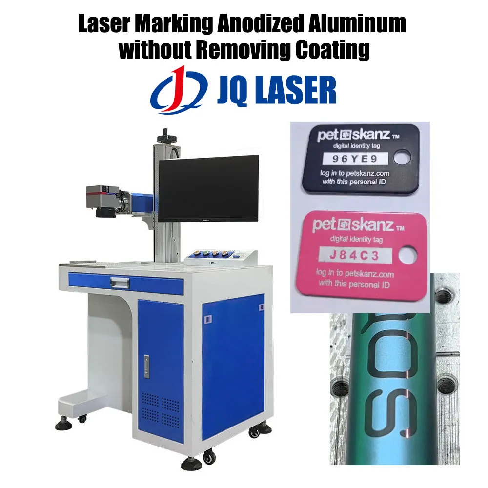
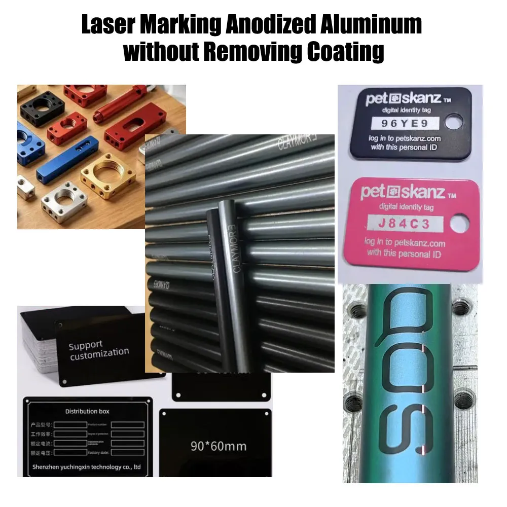
The goal is simple: put a readable, permanent mark on anodized aluminum without stripping the anodized layer or exposing the aluminum underneath. For many black-anodized parts, a properly configured MOPA fiber laser is a good starting point. But do not assume that every anodized finish will respond in the same way.
Before choosing a machine, confirm the coating type, color, sealing condition and required mark appearance. Then test pulse duration, frequency, power, speed, hatch spacing, focus, pass count and the actual surface condition. These variables work together. Changing only the power is rarely enough.
First, understand what “mark without removing the coating” actually means
There are two different jobs that are often described with the same words.
- Coating-preserving marking: the laser changes the appearance of the anodized surface or the material within the oxide layer while keeping the coating substantially intact. The aim is a dark, gray or otherwise contrasting mark without exposing bare aluminum.
- Laser ablation / coating removal: the laser removes some or all of the anodized layer. The aluminum underneath becomes visible, often producing a bright or silver-colored mark on a dark surface.
These are not interchangeable processes. If your drawing says “do not remove anodizing,” a bright silver mark created by stripping the black coating is not an acceptable substitute, even if the code is easy to read.
For this guide, we focus on coating-preserving marking. The process window depends heavily on the anodizing process, dye, coating thickness, sealing and laser source. A recipe that works on one batch may not work on another.
Which anodized aluminum parts can benefit from this process?
We commonly see this requirement in applications where appearance, identification and surface protection all matter. The following are practical target applications, not a guarantee that every part can be marked with the same settings.
1. Black-anodized aluminum nameplates
Equipment manufacturers often need a logo, model number, serial number, electrical rating or QR code on a black nameplate. A dark mark on a dark background may be difficult to read, so a high-contrast gray or black-on-black effect is not always the right target. Define the required contrast before testing. If a bright silver mark is acceptable, coating removal may be the intended process instead.
2. Consumer electronics housings
Aluminum housings, control panels and decorative covers may need small logos, product IDs or regulatory information. Here, a visible heat-affected halo, rough edge or uneven shade can make an otherwise readable mark unacceptable. Use the real housing finish, not a generic anodized coupon, for final approval.
3. Automotive and motorcycle components
Brackets, housings, control knobs and aluminum accessories may need part numbers, batch IDs or traceability codes. If the component is exposed to moisture, cleaning chemicals or road salt, the customer should verify coating integrity and corrosion performance after marking. Visual inspection alone is not enough.
4. Industrial control panels and machine components
Operators need labels that remain readable after routine cleaning. Marking can be used for button labels, adjustment scales, warning symbols and serial numbers. For frequently handled surfaces, test abrasion and chemical resistance using the customer’s actual cleaning method.
5. Aluminum fixtures, jigs and tooling
Fixtures and production tools often need asset numbers, location codes or calibration IDs. A shallow, readable mark may be enough. Avoid unnecessary engraving depth if the requirement is to retain the anodized coating.
6. Architectural and decorative aluminum parts
Trim pieces, handles and decorative panels may require logos or identification without changing the finish around the mark. Color consistency between batches matters. Approve samples under the same lighting conditions in which the finished product will be inspected.
7. Electronic equipment enclosures
Data Matrix codes, serial numbers and small text can support repair tracking and production traceability. For small codes, test the final code size, cell geometry and reading performance. A mark that looks sharp to the eye may still fail a barcode verifier.
Why a MOPA fiber laser is worth testing first
A conventional pulsed fiber laser can mark many anodized aluminum surfaces, especially when the required effect is coating removal or a conventional contrast mark. However, when the job requires fine control over the interaction with the anodized layer, a MOPA source is a sensible configuration to evaluate.
MOPA sources allow the pulse duration to be adjusted independently within the source’s specified range. That gives the process engineer more room to test how energy is delivered to the surface. It does not automatically mean that a MOPA machine will preserve every coating. The correct result still depends on the coating and the complete optical and process setup.
A real published starting example
Trotec publishes the following example for black marking on anodized aluminum using a 20W MOPA laser:
| Parameter | Published example | How to interpret it |
|---|---|---|
| Laser power | 50% | Percentage of the specific machine’s available output, not a universal wattage. |
| Marking speed | 1,500 mm/s | A starting value for that published setup, not a guaranteed production speed. |
| Frequency | 200 kHz | Pulse repetition rate in the example. |
| Pulse duration | 8 ns | Short pulse duration used in the published MOPA example. |
| Focus | In focus | Use the specified focus condition as the first test point. |
| Hatch spacing | 0.001 mm for rich black; 0.002–0.005 mm for gray | Smaller spacing creates a darker result in this particular example. |
| Passes | 1 | One pass in the published setup. |
Important: this is a reference recipe from another manufacturer’s application guidance. It is not a guaranteed JQ Laser setting. Trotec also warns that anodized layers can vary considerably. Use the values as a controlled first experiment, then verify the coating and mark on your own parts.
8 process variables to test before production
Variable 1: Pulse duration
Why it matters: pulse duration changes how laser energy is delivered during each pulse. For a coating-preserving process, the objective is to create the required visual change without driving the surface into unwanted ablation, roughening or coating damage.
How to test: if your MOPA source supports adjustable pulse duration, select several values within the source’s actual specification. For a JPT M7 30W example, the published pulse-width range is 2–350 ns. Start with the short-pulse region around the published Trotec example, then test nearby values while holding the other variables constant.
What to record: mark shade, uniformity, edge quality, visible surface change and whether the coating remains continuous.
Common mistake: assuming the shortest possible pulse always produces the best mark. The correct pulse duration depends on the anodizing system and the desired shade.
Variable 2: Pulse frequency
Why it matters: frequency determines how many pulses are delivered per second. At the same average power, changing frequency changes the energy available per pulse and the spacing between pulses at a given scanning speed.
How to test: use a small frequency matrix within the laser source’s supported range. For the published Trotec example, the reference is 200 kHz. Do not copy this value blindly to a different source. Keep pulse duration, speed, power and hatch spacing fixed during each comparison.
What to record: contrast, surface texture, heat-related discoloration and consistency across the marked area.
Common mistake: comparing frequency settings while also changing speed and power. If several variables move at once, you will not know what improved or damaged the result.
Variable 3: Average laser power
Why it matters: more average power can increase the amount of energy delivered to the workpiece, but it can also push the process toward coating removal. The goal is not to maximize power. It is to find the lowest stable energy input that meets the mark specification.
How to test: begin with a conservative power range and increase in controlled steps. Trotec’s 20W MOPA example uses 50% power. Treat that as a reference for its own machine and material, not as a universal setting.
What to record: shade, uniformity, coating damage, mark repeatability and cycle time.
Common mistake: choosing a higher-wattage source because the customer wants a darker mark. A 50W source does not automatically create a better coating-preserving mark than a 20W MOPA source. It may simply make it easier to exceed the safe process window.
Variable 4: Marking speed
Why it matters: speed affects the time the beam spends over each part of the surface. If speed is too high, the mark may be weak or uneven. If it is too low, local energy input may become excessive.
How to test: use a speed ladder around a sensible first setting. The published Trotec example uses 1,500 mm/s. Test faster and slower settings while holding the other variables constant.
What to record: mark shade, uniformity, edge definition, surface damage and measured cycle time.
Common mistake: using the scanner’s maximum advertised speed as the actual production rate. Scanner speed is not the same as accepted parts per hour. Artwork complexity, hatch density, code size, fixture loading and inspection all affect output.
Variable 5: Hatch spacing and fill strategy
Why it matters: hatch spacing controls the distance between adjacent scan lines. It has a direct effect on how much of the surface is treated and how dark or uniform the result appears.
How to test: create a hatch-spacing matrix. Trotec’s published example uses 0.001 mm for a rich black result and 0.002–0.005 mm for gray tones. These are unusually fine spacing values and should be interpreted in the context of the specific software and machine setup. Confirm that the software accepts the values as intended.
What to record: shade, banding, line overlap, processing time and any sign of coating removal.
Common mistake: choosing the smallest possible hatch spacing without checking cycle time. A darker mark may take substantially longer and may not be necessary for the customer’s actual readability requirement.
Variable 6: Focus position and lens selection
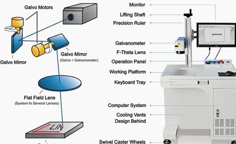
Why it matters: focus affects spot size and energy distribution. The lens determines the marking field and influences spot size and achievable detail. A lens that is too large for the job may reduce the fine-detail performance the customer expects.
How to test: first establish the correct focal plane using the supplied focus method. Then test small, controlled focus offsets only if the initial result requires adjustment. Trotec recommends an F-254 lens for its 20W MOPA example. That recommendation belongs to its specific optical setup; it is not a universal lens requirement.
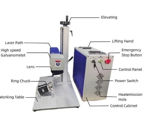
JQ Laser configuration reference: the JQ fiber laser series lists a standard 110 × 110 mm marking field, with optional 150 × 150, 175 × 175, 200 × 200 and 300 × 300 mm fields. Confirm the actual lens and field size on the quotation because the field size affects the optical configuration.
What to record: mark uniformity across the field, smallest readable character, code quality and focus repeatability.
Common mistake: selecting the largest field just because it covers the whole part. A larger field may change the spot size and detail capability. Test the real part at the required marking position.
Variable 7: Number of passes and scan direction
Why it matters: repeated passes increase total energy input. Bidirectional filling can reduce processing time, but the return scan and line alignment may influence the visual result.
How to test: begin with one pass, as in the published Trotec example. If the result is too light, test a second pass only after checking whether the first pass has changed the coating. Compare one pass with two passes using the same settings and artwork. Also compare bidirectional and unidirectional filling if banding or directional texture appears.
What to record: shade change between passes, surface integrity, repeatability, cycle time and any visible line pattern.
Common mistake: using multiple passes to compensate for the wrong pulse or hatch settings. More passes can increase the risk of removing or damaging the coating.
Variable 8: Anodizing condition, dye, thickness and sealing
Why it matters: the laser does not interact with a generic material called “anodized aluminum.” It interacts with a specific anodized finish. Dye type, coating thickness, sealing, alloy, surface roughness and supplier process can all change the result.
How to test: ask the anodizing supplier for the coating specification, color, nominal thickness, sealing condition and batch information. Test parts from more than one production batch if the job will run over time. Include the customer’s actual finished component in the approval test.
What to record: supplier and batch, coating specification, initial appearance, laser settings, mark appearance and post-marking test results.
Common mistake: approving a process using a sample plate from one supplier and then running parts from another anodizing supplier without requalification.
How to run a useful sample test
Do not send a supplier one small logo and ask whether the machine can mark anodized aluminum. That test does not answer the questions that matter in production.
- Send the real part. Include the same alloy, anodizing color, coating specification and surface finish as the production component.
- Define the target. Specify whether the required result is black, gray, white/silver or another appearance. State clearly whether any coating removal is prohibited.
- Define the acceptance criteria. Include contrast, smallest character, code readability, mark location, surface appearance and maximum acceptable cycle time.
- Run a controlled parameter matrix. Change one variable at a time first. Once a promising window is found, test combinations around that window.
- Inspect the coating. Use an appropriate method to check whether the oxide layer has been removed or damaged. For critical parts, use coating-thickness or cross-sectional evaluation by a qualified lab.
- Test durability. Use the customer’s actual abrasion, cleaning, chemical exposure or corrosion test requirements. Do not assume that a visually good mark has passed durability testing.
- Repeat the test. Run samples from different locations or batches to check consistency.
- Save the process record. Record source model, lens, field size, pulse duration, frequency, power, speed, hatch spacing, focus, passes, software version and sample batch.
A good sample report should show the actual part before and after marking, close-up images, machine configuration, complete settings and the test results. If a supplier cannot provide the settings and test conditions, you cannot reliably reproduce the result on your production floor.
Procurement checklist: what to confirm before buying
Use this checklist when comparing laser marking machine quotations. The goal is to buy a process that meets your coating and readability requirements, not simply a machine with a higher wattage number.
1. Confirm that coating preservation is a written requirement
- Applicable condition: parts where anodizing must remain substantially intact after marking.
- Evidence / test: put “no intentional coating removal” in the drawing or acceptance specification. Ask for sample evidence and an agreed coating-integrity test.
- Limitation: “No visible damage” is not proof that the oxide layer remains intact. Critical corrosion or insulation requirements need suitable testing.
2. Ask whether the quoted source is MOPA or conventional pulsed fiber
- Applicable condition: dark or gray marks where pulse-duration adjustment may help control the surface interaction.
- Evidence / test: request the exact laser source model and its official datasheet. Confirm adjustable pulse duration, frequency range and rated output power.
- Limitation: MOPA is a useful process option, not a guarantee of coating preservation. The material and sample test still decide.
3. Confirm the actual pulse-duration and frequency ranges
- Applicable condition: applications requiring a controlled contrast window or fine adjustment of the marking effect.
- Evidence / test: check the source model’s datasheet and ask the supplier to show the settings used in the sample test.
- Limitation: different source models have different ranges. Do not assume every 20W or 30W MOPA source has identical specifications.
4. Match the lens and marking field to the part
- Applicable condition: nameplates, small electronics housings, large control panels or parts with marks positioned far from the center of the field.
- Evidence / test: ask for the lens model, field size and sample result at the actual marking position. Check detail and uniformity across the required area.
- Limitation: a larger field is not automatically better. Optical spot size and detail capability can change with the lens.
5. Require a real-part sample test, not only a demonstration video
- Applicable condition: every production application where the anodized finish, color or coating supplier matters.
- Evidence / test: send production parts and request a settings sheet, close-up photos and a test report.
- Limitation: a sample on a different anodizing batch or color cannot fully qualify your production process.
6. Check code readability and marking quality
- Applicable condition: serial numbers, QR codes, Data Matrix codes, logos and small text.
- Evidence / test: test the smallest required code on the actual part. Use a suitable barcode verifier if the customer has a formal grading requirement.
- Limitation: visual inspection or a phone scan does not replace a formal verification grade where one is specified.
7. Confirm the production cycle time using accepted parts per hour
- Applicable condition: repeat production, batch marking or integration into an existing production line.
- Evidence / test: time the complete cycle, including loading, positioning, marking, unloading and inspection. Record accepted parts per hour.
- Limitation: the maximum scanner speed in a brochure is not the same as the production rate.
8. Agree on durability and coating acceptance tests
- Applicable condition: parts exposed to cleaning, abrasion, moisture, chemicals or corrosion requirements.
- Evidence / test: agree on the customer’s actual test method and acceptance criteria before ordering. Use a qualified laboratory when the specification requires it.
- Limitation: laser marking alone does not establish compliance with a corrosion, salt-spray or chemical-resistance standard.
9. Confirm the complete machine configuration
- Applicable condition: any purchase where the supplier offers multiple source brands, lenses, controllers or working-table options.
- Evidence / test: request a written bill of configuration listing source brand and model, galvo, lens, controller, software, field size, rotary axis and accessories.
- Limitation: a general product-page specification may describe a series, not the exact machine in your quotation.
10. Check safety, extraction and service support
- Applicable condition: enclosed production areas, continuous operation or integration with automated equipment.
- Evidence / test: review the machine’s laser safety enclosure, interlocks, extraction arrangement, electrical requirements, manuals, training and after-sales process.
- Limitation: safety requirements depend on the installation country, machine class and workplace risk assessment. Confirm local compliance before installation.
JQ Laser machine configuration reference
The following are published series-level specifications from JQ Laser’s fiber laser marking machine page. They are useful for initial machine selection, but they do not represent a guaranteed anodized-aluminum process recipe. Confirm the exact source model, lens and configuration in your quotation.
| Item | JQ Laser published series reference | What the buyer should confirm |
|---|---|---|
| Rated power options | 20W / 30W / 50W / 100W | Exact source brand and model on the quotation. |
| Wavelength | 1064 nm | Confirm the source datasheet. |
| Scanner speed | Up to approximately 7,000 mm/s | Actual marking speed and accepted parts per hour on the real job. |
| Standard marking field | 110 × 110 mm | Actual lens and marking field supplied. |
| Optional marking fields | 150 × 150, 175 × 175, 200 × 200 and 300 × 300 mm | Whether the selected field provides the required detail and uniformity. |
| Cooling | Air cooling | Operating environment and source-specific requirements. |
For coating-preserving anodized aluminum marking, ask JQ Laser to quote a MOPA configuration if adjustable pulse duration is part of your process requirement. Do not assume that every machine in the 20W–100W series is MOPA. The source model must be stated on the quotation.
View JQ Laser Fiber Laser Marking Machine | View MOPA Fiber Laser Marking Machine
Comparison table: which setup should you evaluate?
| Configuration / process | Best reason to consider it | What to watch | Recommended next step |
|---|---|---|---|
| 20W MOPA fiber | A sensible first configuration to test for controlled dark or gray marking on suitable anodized finishes. | Actual contrast and coating response depend on the anodizing batch and optical setup. | Start with a real-part sample and a controlled pulse/frequency matrix. |
| 30W MOPA fiber | Worth evaluating when the required cycle time or part size needs more output headroom. | More power does not automatically improve the mark or preserve the coating. | Compare the 20W and 30W samples at the same acceptance criteria. |
| 50W or higher fiber | May suit other production requirements such as faster marking or deeper engraving. | Higher available power can make it easier to exceed a coating-preserving process window. | Buy only after the actual process has been demonstrated and cycle time measured. |
| Conventional pulsed fiber | Can be suitable for many standard anodized aluminum marking or coating-removal jobs. | Pulse control may be less flexible than a MOPA source for certain surface effects. | Test it if the required result is simple and the sample meets the coating specification. |
| Laser coating removal | Suitable when a bright, exposed-aluminum mark is actually required. | This is not the same as marking without removing the coating. | Confirm that the drawing permits coating removal and define the acceptable removal depth. |
Our buying advice: if the main requirement is a dark mark with the anodized layer retained, begin by testing a 20W MOPA configuration on the customer’s real parts. Compare a 30W MOPA only if the 20W process cannot meet the required cycle time or mark specification. Do not buy 50W or 100W simply because the number looks safer or more powerful.
What should be included in a supplier’s sample report?
Before placing a machine order, ask the supplier to provide the following information. It makes the result traceable and reduces arguments after installation.
- Part material and alloy, if known.
- Anodizing supplier, color, coating thickness specification and sealing condition, if available.
- Laser source brand and exact model.
- Laser power, pulse duration, frequency, speed, hatch spacing, focus position and pass count.
- Lens model and marking field.
- Photographs of the full part and close-up of the marked area.
- Code readability or verification result, where applicable.
- Coating-integrity and durability test method, result and limitations.
- Cycle time and the measurement method used.
- Sample date and material batch identification.
If the coating thickness, corrosion resistance or electrical insulation is critical, a photograph is not sufficient evidence. Arrange the relevant test with the coating supplier or a qualified testing laboratory.
Frequently asked questions
Can a fiber laser mark anodized aluminum without removing the coating?
Yes, certain fiber laser processes can create a contrasting mark while keeping the anodized layer substantially intact. MOPA fiber lasers are worth testing when adjustable pulse duration is needed. The result depends on the coating, dye, sealing and laser settings. A real-part test is essential.
Is MOPA always necessary for anodized aluminum?
No. Conventional pulsed fiber lasers can mark many anodized aluminum parts, especially when coating removal is acceptable. MOPA is worth considering when you need more control over pulse duration and the surface effect. The sample result should decide the configuration.
Can I use a 20W MOPA laser for black marking?
A published Trotec application example uses a 20W MOPA laser for black marking on anodized aluminum. Its example settings are 50% power, 1,500 mm/s, 200 kHz, 8 ns, one pass and a 0.001 mm hatch spacing for a rich black result. These settings are not universal and must be tested on the actual coating.
Will a 30W or 50W laser produce a darker mark than a 20W laser?
Not necessarily. The result depends on pulse duration, frequency, scan speed, hatch spacing, focus and the anodized finish. A higher-power source can increase process flexibility or throughput, but it can also remove or damage the coating if the process is not controlled.
Does black anodized aluminum give the best contrast?
Dark anodized finishes can provide a useful background for bright marks, while selected MOPA processes can create dark marks on suitable anodized surfaces. The best visual result depends on the requested mark color and the actual dye and coating. Define the target appearance before testing.
Can I mark clear or natural anodized aluminum?
It may be possible to create a visible mark, but the contrast can be weaker or different from dyed anodized aluminum. Test the actual surface finish and do not assume that a setting developed for black anodizing will work on clear anodizing.
How can I confirm that the anodized layer has not been removed?
Start with visual and microscopic inspection, but use a suitable coating-integrity or thickness evaluation when the requirement is critical. For corrosion-sensitive parts, perform the specified corrosion or chemical exposure test. The test method should be agreed before production.
Can the mark survive cleaning and abrasion?
It depends on the marking process and the coating. Run the customer’s actual cleaning and abrasion tests on marked samples. Do not assume that a dark appearance automatically means the mark will survive every chemical or wear condition.
What information should I send for a sample test?
Send the actual anodized part, the target mark artwork, the required mark color, the minimum code or character size, the production cycle-time target and any coating-integrity or durability requirements. Include the anodizing specification and batch information if available.
How do I choose between 20W and 30W MOPA?
Compare both on the same part using the same acceptance criteria. If 20W achieves the required contrast, coating integrity and cycle time, the extra power may not add value. Choose 30W when the tested process demonstrates a real production benefit.
References and technical sources
The technical examples and machine data in this article are traceable to the following sources. Manufacturer application settings are examples, not universal process guarantees.
- Trotec – Black marking on anodized aluminum. Published 20W MOPA example settings and notes on variation between anodized layers.
- JPT – 30W MOPA Fiber Laser Source. Example source model YDFLP-E-30-M7-S-R, with 1064 nm wavelength, adjustable 2–350 ns pulse duration and 1–4000 kHz frequency range. Confirm the exact source model before using these specifications in a quotation.
- European Patent EP4440845A1 – Method for surface contrast laser marking of anodised aluminium or aluminium alloy parts. Describes a surface-contrast process intended to form a dark mark within the anodic layer without piercing it. A patent describes a claimed method; it is not independent proof that every machine or part will achieve the result.
- TRUMPF – Laser Marking Technical Booklet. Explains marking on anodized coatings, including coating removal and marking at or beneath the surface.
- Epilog – FiberMark Manual, Material Settings. Provides anodized aluminum marking examples and notes that anodizing grade and base aluminum alloy affect the result. Its settings belong to the FiberMark platform.
- JQ Laser – Fiber Laser Marking Machine. JQ Laser series-level power options, wavelength, marking-field options, cooling and scanner-speed reference.
Need to mark your anodized aluminum parts?
Send us your actual part or a representative sample, together with the anodizing color, coating specification, target mark appearance and required cycle time. We can help evaluate a suitable fiber laser configuration and arrange a sample test before you make a purchasing decision.
Do not just ask whether a machine can mark anodized aluminum. Ask whether it can produce your required mark while meeting your coating-integrity and durability requirements.
Contact JQ Laser for a Sample Test and Machine Configuration