Many customers new to laser marking machines get nervous as soon as they hear the term “optical path adjustment”: Does this mean I have to disassemble the galvanometer? Do I need to adjust the lenses?
In fact, for the mainstream fiber, MOPA, and UV laser marking machines on the market, more than 90% of the “optical path misalignment” issues encountered in daily use stem from a single cause—the workpiece is not at the focal point. Situations where you actually need to open the marking head and adjust the internal mirrors of the galvanometer are rare, and we recommend doing so only under the manufacturer’s guidance.
This article provides you with a complete set of steps for diagnosis and troubleshooting: first, identify the machine model; then, check for any effects of shipping; next, verify the focal length; and finally, determine whether you need to contact the manufacturer. Junqi Laser machines are shipped with the optical path securely locked and properly adjusted. If the position shifts after long-distance shipping, you can contact us directly for one-on-one video guidance.

Written by LEO — JQ Laser Sales Engineer
I have worked with laser marking applications for more than 10 years, covering metal marking, product identification, fine marking and automation projects. My job is not only to quote a machine. I work with customers to match the laser, material, marking effect, production requirement and machine configuration before the order.
JQ Laser — Jining Junqi Intelligent Technology Co., Ltd.
Table of Contents
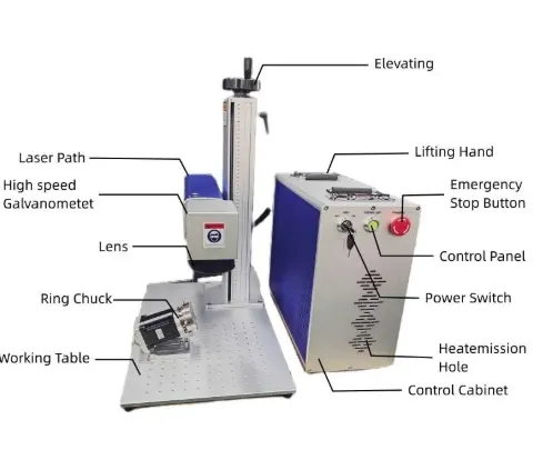
1. First Identify Your Machine Type: What Does Your “Optical Path” Look Like?
Optical path structures vary greatly across different laser technology platforms. Take 30 seconds to determine which category your machine falls into, then decide “what to adjust and what not to adjust.”
| Machine Type | Optical Path Structure | User-Adjustable Parts (Daily Use) | Parts Not Recommended for User Adjustment |
|---|---|---|---|
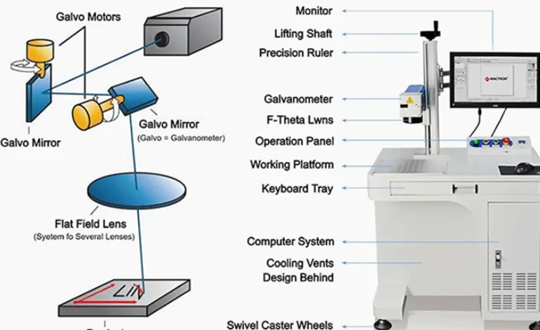
| Fiber / MOPA | Laser delivered via fiber → Galvanometer deflection → F-theta field lens focusing → Workpiece | Lifting height (working distance), red light preview switch, software correction parameters | Internal galvanometer lenses, field lens disassembly, laser interior |
| UV Ultraviolet | Similar to fiber structure, 355 nm wavelength, more sensitive optical components | Working distance, red light preview | Galvanometer/field lens interior, UV optical path cleaning |
| CO₂ | Laser tube → Multiple mirror sets → Focusing lens → Workpiece | Mirror angles, focusing lens height, optical path bracket | High voltage inside laser tube, electrical components |
| Flying / Vision / Automation | Standard machine with added encoders, cameras, sensors | Trigger position, camera field of view, focal length | Overall optical path reference, linkage calibration |
Quick summary: The optical paths of fiber/MOPA/UV machines are basically sealed inside the galvanometer and field lens; CO₂ machines have an open mirror system.
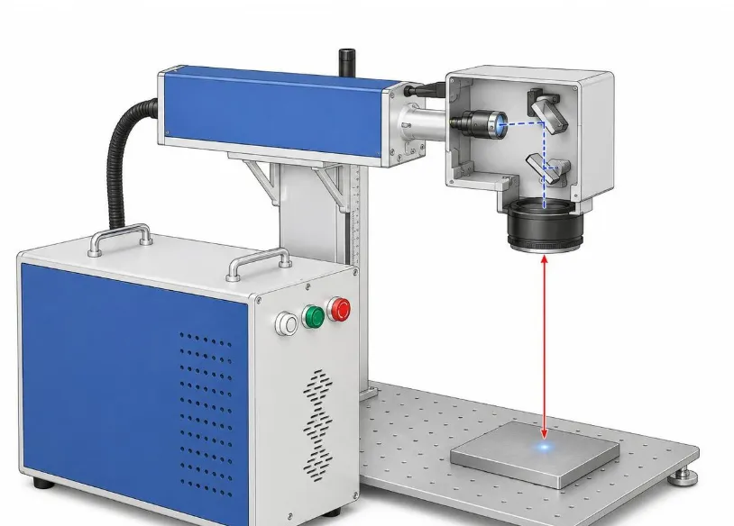
[Diagram: Fiber laser marking machine optical path and focal length illustration]
In this diagram you can see: Laser enters the galvanometer from the fiber, scans through two galvanometer mirrors, then focuses onto the workpiece surface through the F-theta field lens. The red arrow indicates: only the distance from the “workpiece surface” to the “bottom of the field lens” needs adjustment by you; the optical path inside the galvanometer is locked at the factory.
2. What We’ve Already Done For You Before Delivery
As a complete machine assembly, configuration, and debugging factory, Zhuorui Laser completes the following optical path-related work before equipment leaves the factory:
- Selection and matching of core components including laser, galvanometer, field lens, control card, computer, and cooling system;
- Galvanometer and field lens installed in place, rough optical path centering;
- Field lens correction file written into control software to ensure consistent marking at center and edges;
- Red light preview aligned with marking center (if equipped with red light preview function);
- Rated working distance confirmed, test marks made with standard samples;
- Lifting column, marking head, and critical screws tightened;
- Factory function inspection and parameter file saving.
💡 Engineer’s Tip: Many customers worry “Do I need to adjust the optical path myself on a new machine?” Under normal circumstances, standard fiber/MOPA machines arrive fully assembled and calibrated. You only need to confirm focal length and working distance after receipt — no galvanometer disassembly required.
[Image: Equipment assembly and debugging workshop]
The image above shows our workshop assembling, wiring, and debugging complete machines. Optical path installation and rough adjustment are completed at this stage, and screws are tightened.
3. After Long-Distance Transportation: Do These 4 Non-Disassembly Checks First
After long-distance transportation, machines most often experience “position shifting” rather than “broken optical paths.” After receiving your machine, follow the inspection sequence below — 90% of issues can be identified.
Check Screws and Structure
- Check if fixing screws on lifting column and marking head are loose;
- Check if marking head is tilted, sunk, or rotated;
- Inspect cabinet and worktable for obvious deformation or impact damage.
Check External Optical Surfaces
- Check if field lens protective lens is clean and crack-free;
- For fiber models, check if fiber connector (QBH/QCS) is firmly inserted and fiber is not excessively bent;
- Check if red light exit window is blocked.
Power On Low-Power Self-Test
- Without enabling laser output, first turn on red light preview to see if the red dot is approximately centered directly below the field lens;
- Use low power and slow speed to test-mark a simple pattern on scrap material, observe if laser emits and position is roughly normal.
Restore Rated Working Distance
- According to equipment nameplate or field lens specifications, first adjust working distance to rated value;
- Then perform test marking to see if focus is sharp.
💡 Engineer’s Tip: The most common “optical path shifted” issue after transportation is actually the marking head being shaken down a few millimeters. First restore the lifting height to the field lens’s rated working distance — many “blurry, misaligned” problems disappear immediately. This check requires removing no covers.
4. The Most Common “Optical Path Adjustment”: Focal Length/Working Distance
For fiber/MOPA/UV machines, so-called “adjusting the optical path” in daily use almost always means “adjusting working distance.”
4.1 Focal Length ≠ The Focal Length Printed on the Field Lens
The “100 mm,” “160 mm,” or “254 mm” marked on F-theta field lenses is typically the effective focal length, while the actual working distance (distance from the bottom plane of the field lens to the focal plane) will be somewhat smaller than the effective focal length. Differences exist between brands and designs — we recommend referring to the specification sheet included with your field lens.
The table below provides industry reference ranges for common F-theta field lenses, for quick positioning only:
| Field Lens Rated Focal Length | Common Working Distance Range | Common Marking Range | Suitable Applications |
|---|---|---|---|
| F100 | Approx. 90–120 mm | Around 70×70 mm | Small parts, fine detail, deep marking |
| F160 | Approx. 160–185 mm | Around 110×110 mm | Standard metal nameplates, hardware |
| F210 | Approx. 240–245 mm | Around 150×150 mm | Medium format, batch workpieces |
| F254 | Approx. 290–300 mm | Around 175×175 mm | Larger workpieces, requiring more working space |
▲ Data sources: Thorlabs China “F-Theta Scan Lenses,” CKD Laser “F-Theta Lens,” DayOptics “1064nm Laser F-theta Lenses” product specification sheets, used to illustrate the difference between rated focal length and actual working distance as well as common reference ranges. For specific values, please refer to the manufacturer’s specification sheet for your equipped field lens.
4.2 How to Quickly Find the Best Focal Point
- Use a ruler or caliper to measure the distance from the bottom plane of the field lens to the workpiece surface;
- First adjust the height to near the rated working distance;
- Use low power and medium speed to mark a small circle or thin line about 1 mm in size;
- Move up or down approximately 0.5 mm each time, marking 3–5 points consecutively;
- Observe with a magnifying glass or microscope — the thinnest, sharpest point with the fewest burrs is the optimal focal point.
[Diagram: Measuring working distance from field lens bottom plane to workpiece surface with calipers]
The diagram above illustrates the method for measuring working distance: place one end of a caliper or ruler against the bottom plane of the field lens, read to the workpiece surface at the other end, to obtain the current working distance. First adjust the height to near the rated value, then use test marking to find the optimal focal point.
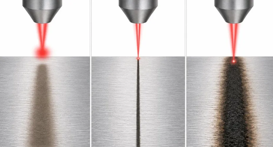
[Diagram: Three focal states comparison — out of focus (too far), in focus, out of focus (too close)]
From left to right: working distance too large (lines become light and fuzzy), correct focus (lines thinnest and sharpest), working distance too small (lines too thick, blackened, or even burned). When finding focus, you fine-tune up and down on the workpiece surface to find that middle state.
💡 Engineer’s Tip: Don’t adjust too much at once when finding focus. Field lens depth of focus is very short, especially for F100 and F160 — a 0.3 mm difference can make lines noticeably thicker. We recommend starting from the rated distance, trying 3 times in each direction, and recording results — this is much faster than “going by feel.”
4.3 Optimal Focal Point Shifts for Different Materials and Target Effects
Even with the same fiber laser machine, parameters are not fixed:
- Black marking on stainless steel surfaces: Focal point is typically at or slightly above the workpiece surface;
- Deep engraving on stainless steel: Focal point slightly sinks into the workpiece surface, requiring higher power, slower speed, and multiple scans;
- Shallow marking on aluminum: Power cannot be too high, focal point should be at the surface;
- Plastics / coatings / composite materials: You must test on samples first, as different materials are very sensitive to heat effects.
▲ Data source: Beijing JCZ Technology Co., Ltd. “EZCAD2 Software Operation Manual,” used to illustrate the interactive relationship between focus, power, speed, frequency, and material effects in control software.
5. What to Do When Red Light Preview Shifts
The red light preview is a visible auxiliary positioning light — it and the actual laser output are two separate systems. A shifted red light does not mean the laser optical path has shifted.
[Diagram: Red light preview spot below field lens]
The diagram above illustrates the function of red light preview: a visible red spot appears below the field lens to assist in positioning the marking area. Red light position and actual marking position may have slight deviations and need to be judged separately.
5.1 First Distinguish Between “Red Light Shift” and “Marking Shift”
| Phenomenon | Meaning | Handling Direction |
|---|---|---|
| Red dot is centered, marking position is also correct | Both are normal | Continue working |
| Red dot shifted, but marking position is correct | Red light preview needs calibration | Check software red light calibration function or contact manufacturer |
| Red dot shifted, marking position also shifted | Possibly workpiece not aligned, coordinate system offset, or optical path reference actually moved | First check fixture/coordinates, then confirm with test marking |
| No red light | Red light switch not turned on or red light module not powered | Check software switch and wiring |
5.2 Red Light Calibration Boundaries
- If your control software has a “red light preview correction” function and you have received training, you can perform small-range software calibration according to the equipment manual;
- If red light shift occurs after long-distance transportation, or the shift amount is large, we do not recommend disassembling the machine yourself to adjust the red light module;
- Equipment configured with “dual red light,” “dual infrared,” or “assisted focusing” may have different adjustment logic — refer to your equipment manual.
💡 Engineer’s Tip: Many beginners mistake “red dot not centered” for “laser shifted” and end up taking apart the galvanometer. In reality, often it’s just the red light module loose by 1 mm, or red light offset parameters accidentally changed in software. Do a test mark first: if marking position is correct, only adjust the red light; if even marking is shifted, then consider optical path reference issues.
6. When Do You Actually Need to Touch the Internal Optical Path?
The internal optical path refers to galvanometer lenses, field lens installation position, beam entry angle into the galvanometer, etc. These parts are precision-made and dust-sensitive — ordinary operators should not disassemble or assemble them themselves.
6.1 Contact the Manufacturer If Any of the Following Occur
- Under the same parameters, the marking area center is clear but edges are obviously blurry, and focal point issues have been ruled out;
- The entire marking area shifts to one side, and software correction cannot bring it back;
- The machine was hit, dropped, or the marking head is obviously displaced after transportation;
- Field lens protective lens is intact, fiber is not bent, but repeated test marking shows consistent directional offset or deformation.
6.2 What Internal Optical Path Adjustment Involves
Manufacturer engineers will, as appropriate:
- Check if the galvanometer mounting base is loose or tilted;
- Open the galvanometer housing, check if galvanometer motors and reflective lenses are stuck or displaced;
- Reconfirm the center position of the beam entering the galvanometer;
- Re-write field lens correction files;
- Recalibrate red light preview with marking center;
- Retest center and edge consistency with standard samples.
💡 Engineer’s Tip: Galvanometer lenses have servo coils and precision bearings — once screws are moved, entire scanning linearity changes. It’s not a matter of “tightening two screws.” When you suspect internal optical path issues, we recommend first taking a video for us: red light position, test marking effect, machine’s current height and screw status. Many cases can be judged via remote video — whether it’s just focus adjustment or actually requires factory return.
7. Common Misconceptions and Safety Boundaries
7.1 Common Misconceptions
- Misconception 1: Higher power = deeper focal depth. Depth depends on power density, scanning speed, repetition count, and material absorption rate — simply turning up power won’t make marking deeper.
- Misconception 2: All field lenses have the same working distance. Even with the same F160 rating, actual working distance can differ by 10–20 mm between manufacturers — you must check the specification sheet.
- Misconception 3: You can align the optical path by loosening a few screws yourself. Once galvanometer screws are loosened, scanning angle, field lens correction, and red light reference are all affected.
- Misconception 4: Use a mirror or reflective sheet to look at the light spot. This is extremely dangerous — reflected light can directly enter your eyes.
- Misconception 5: No red light means the laser is broken. Red light is only auxiliary light — the red light circuit is independent and cannot be used to infer laser status.
7.2 Safety Boundaries
- Fiber laser (around 1064 nm near-infrared) and ultraviolet laser (355 nm) are invisible or extremely weak to the naked eye — never attempt to “find the light” with your eyes;
- Before troubleshooting, turn off laser output; use appropriate lighting when checking external wiring, screws, and lenses;
- Operations requiring opening of galvanometer or laser housings should be performed by qualified personnel;
- According to GB 7247.1-2012 “Safety of laser products — Part 1: Equipment classification and requirements,” laser marking machine output typically falls into high laser classes — use protective shields or wear laser safety glasses for the corresponding wavelength during operation.
▲ Data source: National Standard GB 7247.1-2012 “Safety of laser products — Part 1: Equipment classification and requirements,” used to explain laser product safety classes and protection requirements.
8. Checklist (Bookmarkable)
| Scenario | Check Items | Pass Criteria |
|---|---|---|
| Receiving new machine | Are screws loose? Is marking head straight? Is protective lens clean? | Stable structure, no visible damage |
| After long-distance transportation | Has lifting height returned to rated working distance? Is red light centered? Is low-power test marking normal? | Sharp focus, position approximately centered |
| Before daily marking | Is working distance correct? Is fixture tightened? Is workpiece flat? | Test marking effect consistent with last time |
| When marking becomes blurry | First check focus, then check lenses, finally consider optical path reference | Marked improvement after focus restoration |
| When suspecting internal optical path issues | Take video: red light position, test marking effect, screw status, machine model | Contact manufacturer for remote judgment, do not disassemble yourself |
9. FAQ
Q1: Do I need to adjust the optical path myself after receiving a new laser marking machine?
A: Standard fiber/MOPA/UV machines complete optical path assembly, calibration, and locking before leaving the factory. Users typically only need to confirm working distance and red light preview function normally. If obvious shift occurs after transportation, we recommend contacting the manufacturer for remote guidance.
Q2: Is the 160 mm marked on the field lens exactly the working distance?
A: Not necessarily. 160 mm is typically the effective focal length; actual working distance is generally smaller — specifics depend on the field lens specification sheet. For example, a common F160 field lens may have a working distance between 160–185 mm, varying by manufacturer.
Q3: If red light is not centered, does that mean the optical path shifted?
A: Not necessarily. Red light is only auxiliary positioning light. If red light is shifted but marking position is correct, usually the red light preview needs calibration; if red light is shifted AND marking position is also shifted, then it may be a coordinate system or optical path reference issue.
Q4: The marking head was knocked crooked after transportation, can I take it apart and adjust it myself?
A: Not recommended. First restore lifting height, tighten screws, then do low-power test marking. If obvious offset remains, contact the manufacturer for one-on-one video guidance. Disassembling the galvanometer or laser yourself may affect warranty and also poses safety risks.
Q5: Are there universal power and speed parameters for finding focus?
A: No. Focal position mainly relates to field lens and workpiece surface position; marking parameters (power, speed, frequency) relate to material and target effect. We recommend first testing on scrap material before batch production.
10. References and Notes
- Beijing JCZ Technology Co., Ltd., “EZCAD2 Software Operation Manual”: Explains interactive relationship between focus, power, speed, frequency, and material effects in control software. https://www.bjjcz.cn/product/159.html
- Thorlabs China, “F-Theta Scan Lenses”: Explains technical parameters of F-theta field lenses including effective focal length, working distance, and scan range. Product Link
- CKD Laser, “F-Theta Lens”: Explains focal length and working distance correspondence for common 1064 nm/355 nm/10.6 µm F-theta field lenses. Product Link
- National Standard GB 7247.1-2012 “Safety of laser products — Part 1: Equipment classification and requirements”: For laser safety classes and protection boundaries.
Note: The optical path structures, operation steps, and parameter ranges described in this article are based on industry-standard laser marking machines and mainstream control software. Differences exist between brands, models, and configurations — please refer to manuals and specification sheets provided with your equipment. Descriptions of factory assembly, debugging, sample testing, and after-sales support are based on Zhuorui Laser’s actual scope of work as a complete machine assembly, configuration, and debugging factory. Operations involving high voltage, laser radiation, and internal components should be performed by qualified personnel. Parameter and effect descriptions in this article represent typical scenarios based on industry standards, not specific customer cases.
Call to Action
Don’t rush to take apart your machine for optical path issues.
Go through the checks in the order above: screws, working distance, red light, low-power test marking. Most cases are just misaligned focus. If shift does occur after transportation, or you suspect internal optical path movement, take a short video of the equipment model, field lens focal length, red light position, and test marking effect and send it to us. We’ll arrange one-on-one video guidance to help you determine whether it can be adjusted remotely or needs factory calibration.
For new machine configurations, MOPA/UV upgrades, rotary axis or vision positioning additions, feel free to send over your materials and target effects — we’ll recommend complete machine configurations based on your actual application.