Customer: Australian Industrial Customer (Name Withheld)
Industry: Metal Packaging / Industrial Cylinder Manufacturing
Application: Batch Number, Production Date and Sequential Serial Number Marking
Laser Source: JPT M7 MOPA 60W
Equipment Type: Automated Fiber Laser Marking System
Manufacturer: JQ Laser – Jining Junqi Intelligent Technology Co., Ltd.
Author: LEO, Sales Engineer at JQ Laser
Technical Review: JQ Laser Application Engineering Team
1. Project Overview: How Can You Mark 30–60 Metal Cylinders Per Minute?
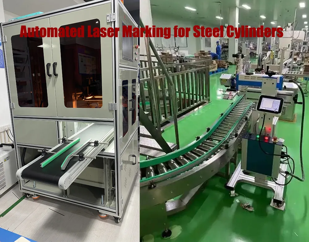
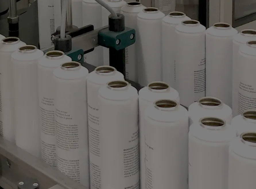
A metal cylinder production line moving at 30–60 units per minute needs more than a standard laser marking machine. The marking system must work with the conveyor, detect each cylinder, position the marking area, generate the correct production information, and communicate with the factory PLC. For this Australian customer’s project, JQ Laser evaluated a 60W JPT M7 MOPA fiber laser configuration for marking batch numbers, production dates, and sequential serial numbers on painted steel cylinders. The proposed solution focuses on high-speed automated marking, production-line integration, operator safety, and electrical compliance requirements for the intended installation market.
2. Customer Background: A High-Speed Cylinder Identification Requirement
The customer is an Australian industrial manufacturer looking for an automated laser marking solution for metal cylinder production.
Unlike a small workshop that marks a few products at a time, this application involves continuous production.
Each cylinder needs identification information that can be associated with its production history.
The requested marking content includes:
- Production dates.
- Batch numbers.
- Sequential serial numbers.
- Other agreed product identification information.
The customer also specified that the machine should integrate with an automatic conveyor system rather than rely on an operator manually placing every cylinder under a laser head.
This introduced several engineering requirements.
| Customer requirement | Project specification |
|---|---|
| Workpiece | 1-lb painted steel cylinders (product description to be confirmed) |
| Laser source | JPT M7 MOPA 60W |
| Marking content | Batch numbers and sequential serial numbers |
| Production target | 30–60 cylinders per minute |
| Material handling | Automatic conveyor |
| Workpiece detection | Automatic cylinder detection |
| Positioning | Automatic marking-position detection and positioning |
| Marking method | Continuous marking while cylinders are moving, if feasible |
| Production control | PLC integration |
| Laser protection | Fully enclosed laser safety system |
| Electrical compliance | Canadian electrical certification or approved field evaluation |
The important point is that these requirements are interconnected.
A laser that produces an excellent serial number at a stationary workstation may not necessarily maintain the same result when the cylinder is moving continuously on a production conveyor.
That is why the entire automation system needs to be evaluated together.
3. Why Did We Recommend a JPT M7 MOPA 60W Laser Source?
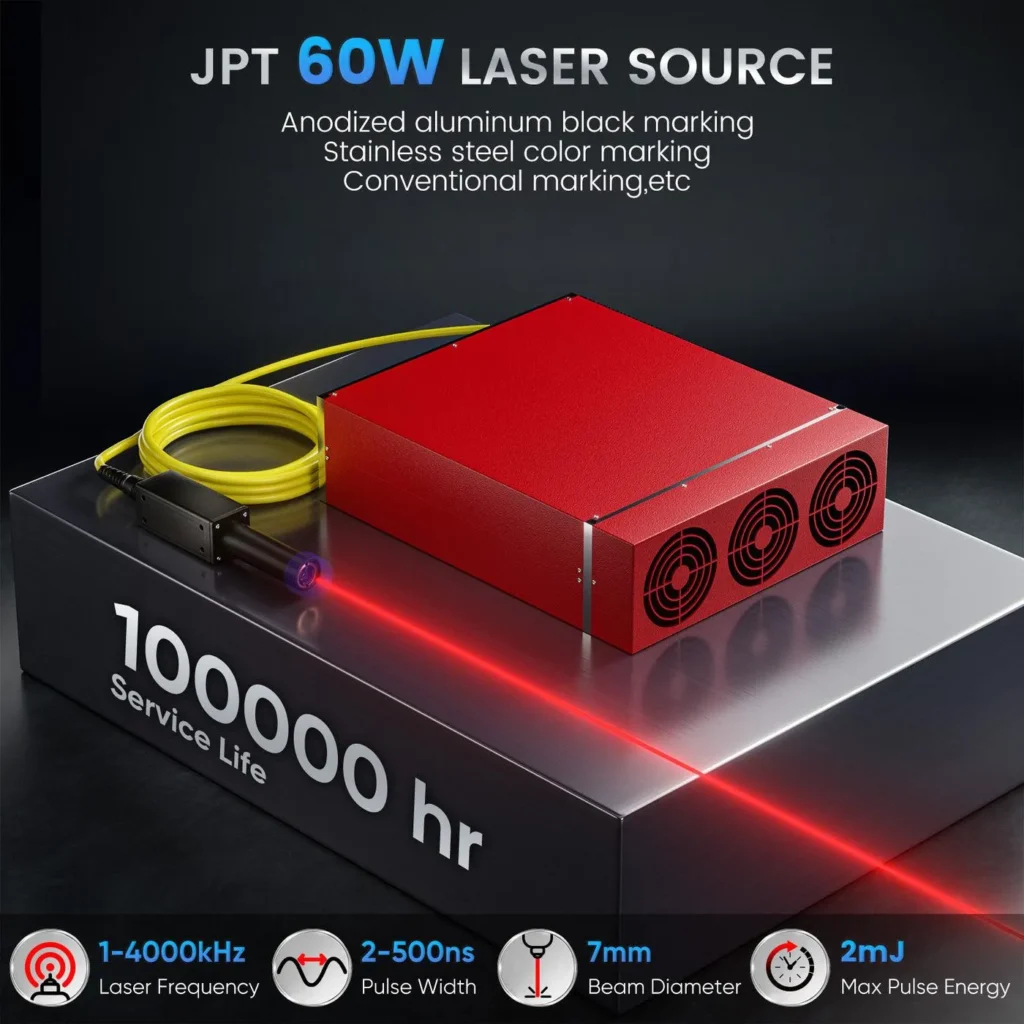
The selected laser configuration for this project is the JPT M7 MOPA 60W fiber laser.
MOPA technology offers adjustable pulse-width control, providing additional flexibility when developing marking parameters for different metal surface conditions.
This is useful when working with painted or coated metal products, where the required result may involve controlled coating removal, surface contrast, or a specific identification appearance.
However, the final marking result depends on the paint formulation, coating thickness, steel surface, and laser parameters. A sample test is essential before finalizing the process.
Reference laser configuration
| Parameter | Project configuration |
|---|---|
| Laser source | JPT M7 MOPA |
| Rated laser power | 60W |
| Laser technology | Pulsed MOPA fiber laser |
| Wavelength | Approximately 1064 nm |
| Pulse-width control | Adjustable, according to the M7 configuration |
| Application | Painted steel cylinder identification |
| Marking content | Production date, batch number, serial number |
| Workpiece handling | Automatic conveyor |
| Control integration | PLC |
| Safety arrangement | Fully enclosed laser system |
Why 60W?
The 60W configuration provides a useful processing-power range for evaluating marking speed and coating interaction.
But higher laser power alone does not guarantee a faster production line.
The actual cycle time also depends on:
- Number of characters per cylinder.
- Character height and font.
- Marking location and available surface area.
- Cylinder spacing on the conveyor.
- Conveyor speed.
- Cylinder rotation and positioning.
- Laser scanning field.
- Required marking contrast.
- Whether marking is performed on a stationary or moving workpiece.
For this reason, the laser source and automation design must be developed around the customer’s actual production conditions.
4. The Main Engineering Challenge: Marking Cylinders at 30–60 Units Per Minute
This was one of the most important requirements in the project.
At 30 cylinders per minute, the production line processes one cylinder every two seconds.
At 60 cylinders per minute, the interval drops to one cylinder every second.
<text color=”secondary” size=”xs”>Calculated from the customer’s requested production rates.</text>
| Production rate | Available interval per cylinder |
|---|---|
| 30 cylinders/minute | 2.00 seconds |
| 40 cylinders/minute | 1.50 seconds |
| 50 cylinders/minute | 1.20 seconds |
| 60 cylinders/minute | 1.00 second |
This interval is not necessarily the laser’s available marking time.
It must also accommodate detection, positioning, triggering, data handling, and any required product spacing.
Challenge 1: Detecting each cylinder accurately
The system needs to recognize when a cylinder enters the marking area.
An appropriate sensor arrangement can provide a trigger signal to the PLC or marking controller.
Depending on the conveyor design, additional sensing may be needed to identify the cylinder’s position and orientation.
Challenge 2: Keeping the marking position consistent
Painted steel cylinders are not always perfectly positioned on a conveyor.
Small variations in position or rotation can move the intended marking area outside the laser’s optimal working zone.
The engineering solution may include:
- Cylinder detection sensors.
- Mechanical guides.
- Positioning fixtures.
- Encoder feedback.
- Vision-based positioning, if required.
- Conveyor synchronization.
The exact configuration depends on cylinder dimensions and the customer’s handling system.
Challenge 3: Maintaining marking quality at production speed
If a cylinder is moving while the laser is marking, the relative movement between the laser beam and workpiece must be controlled.
There are two possible approaches:
Option A: Stop-and-mark operation
The conveyor positions the cylinder at the marking station, stops or indexes it, and triggers the laser.
This approach can simplify positioning and marking synchronization.
However, the conveyor and indexing mechanism must still support the required production rate.
Option B: Continuous dynamic marking
The cylinder remains in motion while the laser marks the identification information.
This requires synchronization between conveyor movement, position feedback, laser triggering, and marking software.
An encoder-based tracking arrangement may be necessary to compensate for workpiece movement.
Dynamic marking is not automatically achievable simply because a machine has a 60W laser. It must be validated against the actual conveyor speed, marking layout, and controller capabilities.
For this project, continuous marking while cylinders are moving was included as a feasibility requirement, subject to engineering verification.
5. How the Automatic Marking System Works
The proposed system architecture connects the laser marking station with the customer’s production line.
Production workflow
- Cylinders enter the automatic conveyor.
- Detection sensors identify the approaching cylinder.
- The PLC receives the sensor signal.
- The system determines the cylinder’s marking position.
- The production control system supplies the required identification data.
- The marking controller receives the batch number and serial number.
- The JPT M7 MOPA 60W laser performs the marking operation.
- The system records or returns the marking status.
- The marked cylinder moves to the next production stage.
Proposed automation architecture
| System component | Main function |
|---|---|
| Conveyor system | Transports cylinders through the marking station |
| Detection sensor | Detects incoming cylinders |
| Encoder | Provides conveyor movement information, if required |
| Positioning mechanism | Maintains the required marking position |
| PLC | Coordinates production-line operations |
| Laser marking controller | Controls marking content and laser execution |
| JPT M7 MOPA 60W | Generates the laser marking process |
| Industrial computer | Manages marking software and job data |
| Safety enclosure | Restricts access to the laser processing area |
| Exhaust system | Removes smoke and process fumes |
| Status feedback | Communicates system operating and fault conditions |
PLC integration: Why does it matter?
For an industrial production line, the laser should not operate as an isolated machine.
It should communicate with the rest of the factory equipment.
The PLC interface can be designed to support signals such as:
- System ready.
- Cylinder detected.
- Marking start.
- Marking complete.
- Marking fault.
- Emergency stop.
- Production data received.
- Conveyor interlock.
The exact I/O arrangement and communication protocol must be confirmed during system integration.
For sequential serial numbers, the customer also needs a reliable data-generation method.
The PLC, industrial computer, or production management system should manage the numbering sequence so that duplicate or missing serial numbers can be identified and controlled.
A marking controller alone should not be assumed to provide complete production traceability.
6. Why a Fully Enclosed Laser Safety System Is Important
The customer specifically requested a fully enclosed laser safety system.
This is an important requirement for an automated industrial installation.
A 1064 nm fiber laser is a Class 4 laser source when operated as an exposed processing system. Its invisible near-infrared radiation can present serious eye and skin hazards.
The enclosure must be designed around the actual laser wavelength, maximum accessible emission, optical configuration, and operating conditions.
Recommended safety considerations
| Safety feature | Purpose |
|---|---|
| Fully enclosed processing area | Prevents direct access to the laser processing zone |
| Laser-rated viewing window, if fitted | Allows safe observation with appropriate protection |
| Door safety interlocks | Prevents hazardous operation when access doors are open |
| Emergency stop | Allows emergency shutdown |
| Safety controller or relay | Manages safety-related functions |
| Conveyor interlocks | Coordinates production and safety conditions |
| Exhaust extraction | Removes process fumes and particulates |
| Warning indicators | Shows machine operating status |
| Safety documentation | Supports installation and risk assessment |
For painted metal cylinders, exhaust extraction is particularly important.
The laser may interact with the paint or protective coating and generate smoke, particulate matter, or decomposition products.
The coating composition and its safety data should be reviewed before production.
The enclosure, interlocks, ventilation, and overall installation should be assessed against the applicable laser safety requirements. A simple protective cover should not be treated as proof of a compliant laser safety system.
7. Canadian Electrical Certification and Field Evaluation
Although the customer is based in Australia, the project requirements specifically include Canadian electrical certification or an approved field evaluation.
This is a separate compliance issue from laser marking performance.
For equipment intended to be installed in Canada, the applicable electrical approval route should be confirmed with the local authority having jurisdiction and the relevant certification or inspection body.
Depending on the equipment and installation, the options may include:
- Certification by an SCC-accredited certification body.
- A recognized electrical product certification mark accepted in the installation jurisdiction.
- An approved field evaluation by an appropriately accredited inspection body.
A field evaluation is not simply a supplier’s internal electrical inspection.
It is an independent assessment of the specific equipment against the applicable requirements.
Electrical compliance points to review
| Item | What needs to be checked |
|---|---|
| Input voltage | Confirm the customer’s site electrical supply |
| Frequency | Confirm 50Hz or 60Hz requirements |
| Electrical enclosure | Wiring, protection, and construction |
| Grounding | Protective earth arrangement |
| Overcurrent protection | Appropriate protective devices |
| Emergency stop | Safety-related shutdown function |
| Control circuit | Electrical control and interlock design |
| Machine documentation | Electrical drawings and component information |
| Certification / evaluation | Acceptance by the relevant Canadian authority |
Important: JQ Laser should not claim that the machine is Canadian-certified unless the exact machine configuration has received the relevant approval. The certification route and responsibility should be agreed before shipment.
8. Sample Testing: What Must Be Verified Before Final Production?
For painted steel cylinders, sample testing is especially important because the paint is part of the marking process.
The laser may need to remove or modify the coating to create a readable identification mark.
The result depends on:
- Paint chemistry.
- Coating thickness.
- Surface preparation.
- Steel substrate.
- Laser pulse parameters.
- Scanning speed.
- Marking geometry.
- Production-line movement.
Recommended sample validation process
Step 1: Receive actual cylinders
We recommend testing the customer’s actual production cylinders rather than using ordinary painted steel plates.
Step 2: Confirm the marking requirements
Confirm the exact production date format, batch number, serial number length, font, character height, and marking location.
Step 3: Develop the laser parameters
The technical team evaluates laser power, frequency, pulse width, scanning speed, and other relevant parameters.
Step 4: Compare marking methods
Test whether the customer requires coating removal, surface discoloration, or another approved marking appearance.
Step 5: Check readability
Inspect the marking visually and verify that the serial numbers can be read consistently.
Step 6: Validate production speed
Test the actual marking layout against the conveyor’s required operating speed.
Step 7: Review the result
Record sample photographs, marking parameters, cycle time, and customer acceptance.
Suggested sample acceptance criteria
| Test item | Acceptance requirement |
|---|---|
| Marking appearance | Agreed contrast and visual quality |
| Character readability | All required characters clearly readable |
| Serial number accuracy | Matches production data |
| Marking position | Within agreed positional tolerance |
| Coating interaction | No unacceptable damage beyond the approved marking zone |
| Marking speed | Meets the agreed production cycle |
| Repeatability | Consistent results across representative samples |
| Safety | Enclosure and interlock functions verified |
| PLC integration | Correct trigger, status, and fault communication |
These are proposed acceptance checks. The actual numerical limits should be agreed with the customer before final machine acceptance.
9. What Makes This Project Different from a Standard Laser Marking Machine?
A standard desktop fiber laser marking machine is designed primarily for individual or small-batch workpieces.
This project requires a production-line marking system.
The difference is significant.
| Feature | Standard desktop machine | Automated cylinder marking system |
|---|---|---|
| Workpiece loading | Manual | Automatic conveyor |
| Position detection | Manual positioning | Sensor-based detection |
| Marking content | Operator input | Production data integration |
| Serial numbering | Manual or software-based | Controlled sequential data management |
| Marking operation | Usually stationary | Indexed or dynamic marking |
| Production control | Local machine operation | PLC integration |
| Safety | Machine-specific enclosure or guarding | Integrated safety enclosure and interlocks |
| Production speed | Depends on operator and marking cycle | Target of 30–60 cylinders per minute |
| Application | General-purpose marking | Dedicated production-line identification |
This is why the project needs to be treated as an automation engineering application rather than simply a request for a higher-power laser.
10. JQ Laser Manufacturing and Project Support
JQ Laser is the export-oriented brand of Jining Junqi Intelligent Technology Co., Ltd., based in Qufu, Jining, Shandong, China.
Our product range includes fiber laser marking machines, MOPA fiber laser systems, UV laser marking machines, CO₂ laser marking machines, and customized laser marking solutions.
For industrial automation projects, we focus on the complete application rather than the laser source alone.
Our project support can cover:
Laser configuration
Selection of laser source, power, lens, and marking field according to the application.
Automation design
Evaluation of conveyor integration, sensors, positioning, PLC signals, and marking synchronization.
OEM customization
Machine branding, appearance, electrical configuration, fixtures, and project-specific equipment arrangements.
Sample testing
Evaluation of the actual workpiece and marking requirements before finalizing the configuration.
Quality inspection
Verification of machine functions, electrical connections, marking results, accessories, and packaging.
Spare parts and technical support
Discussion of replacement optical components, electrical parts, control components, and remote troubleshooting arrangements.
MOQ and delivery arrangements
For standard machines, individual and small-batch orders can be discussed.
For customized conveyor systems and automated marking stations, MOQ and delivery time depend on the project scope, engineering design, component procurement, sample testing, and compliance requirements.
A project-specific quotation should identify:
- Laser source and optical configuration.
- Conveyor and handling arrangement.
- PLC and communication requirements.
- Safety enclosure scope.
- Electrical approval requirements.
- Sample acceptance criteria.
- Spare parts and warranty.
- Production and delivery milestones.
We prefer to confirm these items before manufacturing rather than promise a delivery date before the engineering scope is clear.
11. Results and Project Value: What Should a Successful Installation Deliver?
For this type of application, success should be measured by more than whether the laser can mark a cylinder.
The system needs to work as part of the customer’s production process.
The key performance indicators should include:
- Production throughput: target 30–60 cylinders per minute.
- Marking accuracy: correct production dates and serial numbers.
- Repeatability: consistent marking appearance and position.
- Data integrity: no duplicate or missing serial numbers.
- Line integration: reliable communication with the PLC.
- Safety: effective enclosure and safety interlocks.
- Maintainability: access to technical support and replacement parts.
The 30–60 cylinders-per-minute figure is the customer’s specified production target. Final achieved throughput must be confirmed through an integrated production acceptance test.
The same applies to continuous dynamic marking: feasibility and performance depend on the actual conveyor speed, marking content, positioning accuracy, and synchronization system.
Our objective is to help customers move from a manual identification process to a controlled, automated marking operation that can be integrated into their production environment.
12. Looking for an Automated Laser Marking Solution for Your Production Line?
If your factory needs to mark production dates, batch numbers, serial numbers, or traceability codes on metal containers, cylinders, or industrial components, JQ Laser can help evaluate the right laser and automation configuration.
We recommend starting with your actual workpiece and production requirements.
Send us the following information:
| Project information | What to provide |
|---|---|
| Workpiece | Metal cylinder / can / other component |
| Material | Painted steel / stainless steel / aluminum |
| Coating | Paint type and approximate thickness |
| Marking content | Production date / batch / serial number |
| Production speed | Units per minute |
| Conveyor | Speed and layout |
| Workpiece dimensions | Diameter, height and marking area |
| Marking method | Stationary / moving / to be evaluated |
| Control system | PLC brand and model |
| Destination | Country and electrical requirements |
| Safety requirements | Enclosure and applicable standards |
Let’s discuss your production line.
JQ Laser – Jining Junqi Intelligent Technology Co., Ltd.
Website: https://fiberlasermarking.com/
Email: sales@fiberlasermarking.com
WhatsApp: +86 17277264168
Contact JQ Laser for an Automated Laser Marking Project
Explore Our Fiber Laser Marking Machines
Frequently Asked Questions
1. Can a JPT M7 MOPA 60W laser mark painted steel cylinders?
Yes, it can be evaluated for marking painted steel cylinders. The result depends on the paint formulation, coating thickness, steel substrate, laser parameters, and required appearance. Actual production samples should be tested before finalizing the configuration.
2. Can the system mark 30–60 cylinders per minute?
This is the customer’s specified production target. Achieving it depends on marking content, cylinder spacing, conveyor speed, detection, positioning, laser scanning time, and control synchronization. An integrated production test is required to confirm actual throughput.
3. Can the laser mark cylinders while they are moving?
Potentially, yes. Dynamic marking requires synchronization between the conveyor, encoder or position feedback, marking controller, and laser system. If the required marking time or tracking accuracy cannot be achieved, an indexed stop-and-mark arrangement may be considered.
4. Can the machine automatically generate sequential serial numbers?
Yes, sequential numbering can be implemented through a suitable data-management and control arrangement. The numbering logic should prevent duplication and missing numbers and should be validated with the customer’s production software or PLC.
5. Does the system support PLC integration?
The system can be designed for PLC integration using an agreed I/O or communication arrangement. The PLC model, signal definitions, protocol, and production data interface should be confirmed during engineering.
6. Why is a fully enclosed laser safety system necessary?
An enclosed system helps prevent operator access to hazardous laser radiation during operation. The enclosure, interlocks, viewing windows, exhaust, and safety controls must be designed and assessed according to the laser wavelength and applicable installation requirements.
7. Can the machine meet Canadian electrical certification requirements?
The project can be engineered with the required electrical documentation and evaluation scope in mind. However, the specific machine must receive approval from the relevant recognized certification or field-evaluation body before it can be described as compliant.
8. Can JQ Laser customize the machine for different cylinder sizes?
Yes. Different cylinder dimensions and marking positions may require adjustments to the conveyor, guides, fixtures, detection sensors, and laser marking field. These requirements should be confirmed using actual workpieces.
9. Can the system mark production dates and batch numbers automatically?
Yes. Production information can be supplied through an agreed PLC or industrial computer interface. The system should validate the incoming data and confirm that the correct information is applied to each cylinder.
10. Can JQ Laser provide sample testing before ordering?
Sample testing can be arranged using representative customer workpieces. For painted cylinders, the actual paint system and production surface condition are particularly important.
Related Resources