When you buy a fiber laser marking machine, the manufacturer will normally show you how to operate the machine and adjust the marking parameters.Today, I’d like to introduce to you How to Set Fiber Laser Marking Machine Parameters!
The problem is that you may remember everything during the training, but after using the machine for a few weeks or months, some of the settings are easy to forget.
So in this guide, we’ll go through the main fiber laser marking machine parameters step by step.
A common question from new users is:
How should I set the parameters of a fiber laser marking machine to get a clean and good-looking mark?
The good news is that it is not as complicated as the EZCAD interface may look at first. You don’t need to understand every setting before you can start marking.
For most everyday jobs, you mainly need to understand a few key parameters: speed, power, frequency, laser timing and filling settings.
Below, JQ Laser explains what these parameters actually do and how they affect the final marking result.
Table of Contents
1. Galvo Scanner Settings
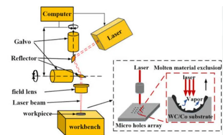
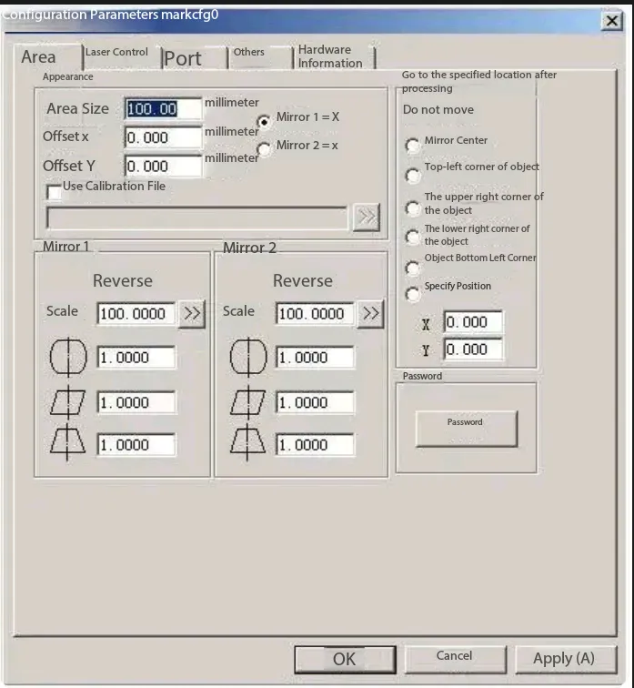
Before adjusting the actual marking parameters, you may see several settings related to the galvo scanner and coordinate system.
These settings are normally configured during machine installation and calibration. In most cases, you should not change them unless you know exactly what you are doing.
Galvo 1 = X
This setting means that scanner output signal 1 from the control card is assigned to the X-axis of the user coordinate system.
Galvo 2 = X
This setting means that scanner output signal 2 from the control card is assigned to the X-axis of the user coordinate system.
Depending on the controller and scanner configuration, these axis assignments may be different, so don’t change them just because the values look unusual.
Y Offset
Y Offset refers to the distance between the center of the galvo scanning system and the center position of the F-theta scanning lens in the Y direction.
This is normally part of the machine calibration rather than a parameter that needs to be adjusted for every marking job.
Use Correction File
This option tells the software to use an external correction file generated by a calibration program such as corfile.exe.
A correction file is used to compensate for optical and scanning errors across the marking field, helping the machine produce more accurate dimensions and shapes.
If your machine has already been calibrated by the manufacturer, leave the correction file settings unchanged unless you are performing a proper calibration procedure.
Reverse
This option reverses the current galvo output direction.
Again, this is generally a machine setup/calibration parameter rather than a normal marking parameter.
2. The Core Fiber Laser Marking Parameters
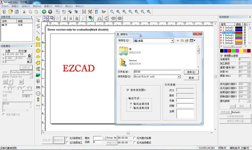
The EZCAD interface can look complicated when you first open it. In actual production, however, there are only a few parameters you will adjust regularly.
The most important ones are:
- Speed
- Power
- Frequency
- Laser timing
- Fill settings
Let’s look at each one.
3. Marking Speed
Speed controls how fast the galvo scanner moves the laser beam across the workpiece.
The unit is mm/s (millimeters per second).
For general marking, the original reference recommends starting around:
1,000–1,500 mm/s
A simple rule to remember is:
Higher speed = faster marking, but generally less energy delivered to each area and a lighter/shallow mark.
Lower speed = more energy delivered to the material and generally a darker or deeper mark.
For example, if you are marking a stainless-steel logo and the result looks too light, you may try reducing the speed or increasing the power.
However, don’t assume that slower is always better.
If you make the speed extremely slow, you may get:
- excessive heat
- discoloration
- burnt edges
- wider lines
- unnecessary cycle time
The correct setting is always a balance between marking quality, contrast, depth and production speed.
Practical starting point
For a new material, don’t immediately try to find the perfect setting.
Start with a small test area and change one parameter at a time.
For example:
| Speed | Power | Result |
|---|---|---|
| 1,500 mm/s | 50% | Faster, lighter mark |
| 1,200 mm/s | 50% | Medium marking effect |
| 1,000 mm/s | 50% | Slower, generally stronger mark |
These are starting examples rather than universal settings. The actual result depends on the laser source, material, surface condition, lens and marking content.
4. Laser Power
Power controls the laser output power used during marking.
In EZCAD, power is normally displayed as a percentage.
For example:
If you have a 30W fiber laser and set the power to 50%, the theoretical output setting corresponds to approximately:
30W × 50% = 15W
This is a simple way to understand the percentage setting.
Generally:
- Harder materials may require higher power.
- Softer or more sensitive materials may require lower power.
- Removing coatings may require a different power/speed combination.
- Deep engraving usually requires more energy than simple surface marking.
However, power percentage should not be treated as a universal conversion to actual optical output power. The relationship depends on the laser source and control system.
So if you change to another laser source or another machine, don’t simply copy the same percentage and expect exactly the same result.
5. Laser Frequency
Frequency controls how frequently the pulsed laser produces laser pulses.
It is normally expressed in kHz.
In simple terms:
Frequency determines how many laser pulses are generated per second.
The original guide recommends approximately:
20–50 kHz
as a general starting range.
But this is only a starting point.
Different materials and marking goals may require different frequency settings.
For example, the combination of:
- speed
- power
- frequency
- pulse characteristics
can affect the appearance, heat input and material removal during marking.
This is why copying a parameter from another machine does not always give the same result.
6. Laser Timing Parameters
In EZCAD, you may see several timing parameters such as:
- Laser On Delay
- Laser Off Delay
- End Delay
- Corner Delay
These parameters control how the laser source and galvo scanner work together.
They are important because the scanner needs time to accelerate, decelerate and change direction while the laser is being switched on and off.
Typical reference settings
The original JQ Laser guide gives the following reference values for a fiber laser marking machine:
| Parameter | Reference Value |
|---|---|
| Laser On Delay | -150 |
| Laser Off Delay | 200 |
| End Delay | 100 |
| Corner Delay | 50 |
These values are machine-dependent reference settings, not universal values for every fiber laser marker.
In most cases, these parameters should already be configured correctly when the machine leaves the factory.
My advice as a practical operator
If your machine is marking normally, don’t change these parameters just because you are experimenting with EZCAD.
Incorrect timing settings can cause problems such as:
- dots at the beginning of lines
- incomplete corners
- overburned corners
- inconsistent line endings
- small gaps
- distorted characters
If you are seeing these problems, first check whether the issue is related to focus, speed, power or the actual marking file. If the problem remains, then check the laser timing settings against the machine manufacturer’s recommended values.
7. Fill Parameters
When you need to fill a logo, letter or graphic instead of marking only its outline, EZCAD uses Fill Parameters.
For most basic applications, you mainly need to understand three settings:
- Angle
- Line Spacing
- Enable
7.1 Fill Angle
The Fill Angle determines the direction of the filling lines.
For example:
- 0° = horizontal filling
- 90° = vertical filling
- +45° / -45° = diagonal filling
Changing the fill angle can sometimes improve the appearance of large filled areas.
For some applications, you can also use multiple fill directions to improve surface uniformity, although this will increase processing time.
7.2 Fill Line Spacing
Line spacing is the distance between two adjacent filling lines.
This is one of the parameters that directly affects both:
Marking quality + marking efficiency
The original guide recommends:
0.05 mm
as a starting value.
A smaller line spacing generally means more filling lines and therefore more laser passes over the same area.
This can produce a denser-looking mark, but it also increases marking time.
A larger line spacing can make the process faster, but if it is too large, you may see visible gaps between the lines.
So don’t simply use the smallest possible value.
For production work, you should choose the line spacing based on:
- material
- marking size
- required contrast
- required surface finish
- production speed
7.3 Enable
The Enable checkbox determines whether the fill setting is actually applied.
- Checked → Fill is enabled.
- Unchecked → The object will not be filled.
This is a simple setting, but it is easy to overlook when you’re testing a new marking file.
8. A Simple Starting Method for New Users
If you’re new to fiber laser marking, don’t try to change five parameters at once.
A much easier approach is to use a small test matrix.
For example, keep the power and frequency unchanged and test several speeds:
1,500 mm/s
1,300 mm/s
1,100 mm/s
900 mm/s
Then choose the result that gives you the best combination of:
- contrast
- edge quality
- depth
- heat effect
- marking time
After that, adjust the power.
For example:
40%
50%
60%
70%
Then compare the results.
This method makes it much easier to understand what each parameter is actually doing.
9. Don’t Forget Focus
Even perfectly configured laser parameters won’t give you a good result if the workpiece is out of focus.
Before changing the parameters too much, check:
Is the workpiece at the correct focal distance?
Incorrect focus can cause:
- blurred lines
- larger spot size
- weak marking
- inconsistent line width
- poor small-character quality
For small text, QR codes and fine graphics, correct focus becomes especially important.
So if your mark suddenly looks blurry, check focus before assuming that the laser power or frequency is wrong.
10. Marking Is Not Just About One Parameter
One of the biggest mistakes new users make is looking for a single “perfect parameter.”
There isn’t one.
A good marking result comes from the combination of:
Speed + Power + Frequency + Focus + Fill + Material + Laser Source
For example, the same 30W fiber laser may use completely different settings for:
- stainless steel
- anodized aluminum
- brass
- copper
- coated metal
- plastic
Even two stainless-steel parts may need different settings if their surface finish or alloy is different.
That’s why we normally recommend sample testing with the customer’s actual material before finalizing production parameters.
11. Recommended Parameter Adjustment Sequence
If you’re setting up a new marking job, this is the order I recommend:
Step 1 — Clean the workpiece
Remove oil, dust and other contamination from the marking area.
Step 2 — Set the correct focus
Make sure the laser is properly focused on the workpiece.
Step 3 — Start with a conservative speed and power
Don’t immediately run the laser at maximum power.
Step 4 — Adjust speed
Find a speed that gives you acceptable contrast and marking efficiency.
Step 5 — Adjust power
Increase or decrease power depending on the required marking effect.
Step 6 — Adjust frequency
Fine-tune the laser pulse behavior according to the material and marking requirement.
Step 7 — Adjust fill
For filled graphics, adjust fill angle and line spacing.
Step 8 — Run a production test
Don’t judge the result from one small sample only. Check several pieces to make sure the result is repeatable.
12. Common Problems and What to Check
| Problem | Things to Check First |
|---|---|
| Mark is too light | Focus, power, speed, frequency |
| Mark is too dark | Power, speed, heat accumulation |
| Mark is too deep | Reduce energy input or increase speed |
| Edges look burnt | Speed, power, frequency, focus |
| Small text looks blurry | Focus, lens, line width, speed |
| Filled area has visible gaps | Fill line spacing |
| Corners look uneven | Laser timing and speed |
| Marking is inconsistent | Focus, material surface, fixture stability |
| Mark is too slow | Speed, fill spacing, marking content |
| Different machines give different results | Laser source, lens, scanner and parameter differences |
13. Final Tips From a Laser Technician
The most important thing to remember is this:
Don’t chase a parameter number. Chase the result you actually need.
The values in a parameter table are only starting points.
If you are marking a stainless-steel logo, for example, your goal may be a clean black mark rather than deep engraving.
If you are removing a coating, the goal may be high contrast without damaging the substrate.
If you are engraving a serial number, readability and consistency may be more important than maximum speed.
So the correct parameter depends on the actual job.
Once you understand what speed, power, frequency, timing and fill do, EZCAD becomes much easier to use.
Set the focus correctly, start with conservative parameters, change one variable at a time, and test the actual material. That’s usually much faster than randomly changing every number on the screen.
If you are still not getting the result you want, send your laser power, material, marking photo and current EZCAD parameters to your machine supplier. A technician can usually narrow down the problem much faster from those four pieces of information.