ROTARY LASER MARKING TECHNICAL GUIDE
How a Rotary Axis Marks Rings and Cylindrical Metal Parts
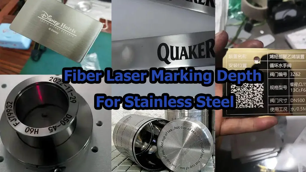
A rotary axis turns a ring, shaft or cylindrical workpiece in a controlled way while the laser marks the exposed surface. The laser controller coordinates the artwork with rotary movement, allowing logos, serial numbers and selected 2D codes to be placed on curved parts. The key is matching the fixture to the workpiece, setting the correct diameter and focus, and checking the marking path before production. A rotary attachment does not automatically solve every curved-surface problem: ring interiors, tapered parts, eccentric workpieces and full-circumference designs may require a special fixture, different optics or a dedicated process test.
How Does a Rotary Axis Work with a Laser Marking Machine?
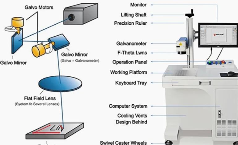
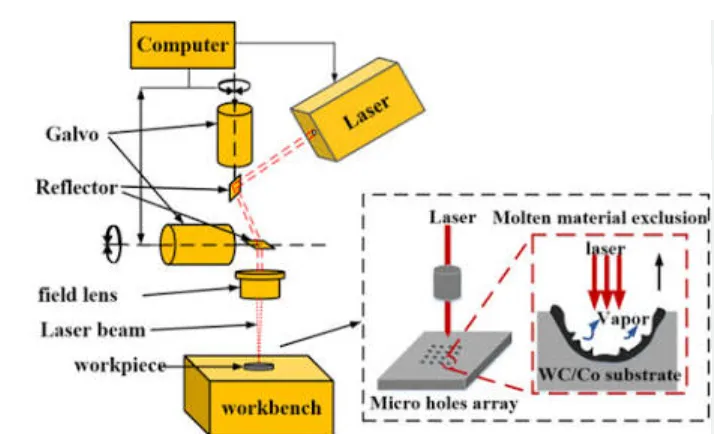
On a flat part, the laser head normally marks within a two-dimensional field while the workpiece stays still. On a cylindrical part, the surface curves away from the laser. A rotary axis adds a controlled rotational movement so the laser can mark a defined section of that curved surface.
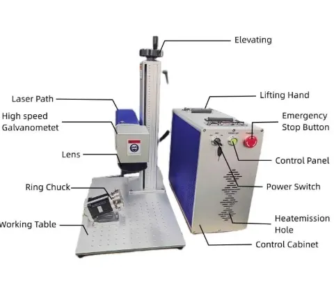
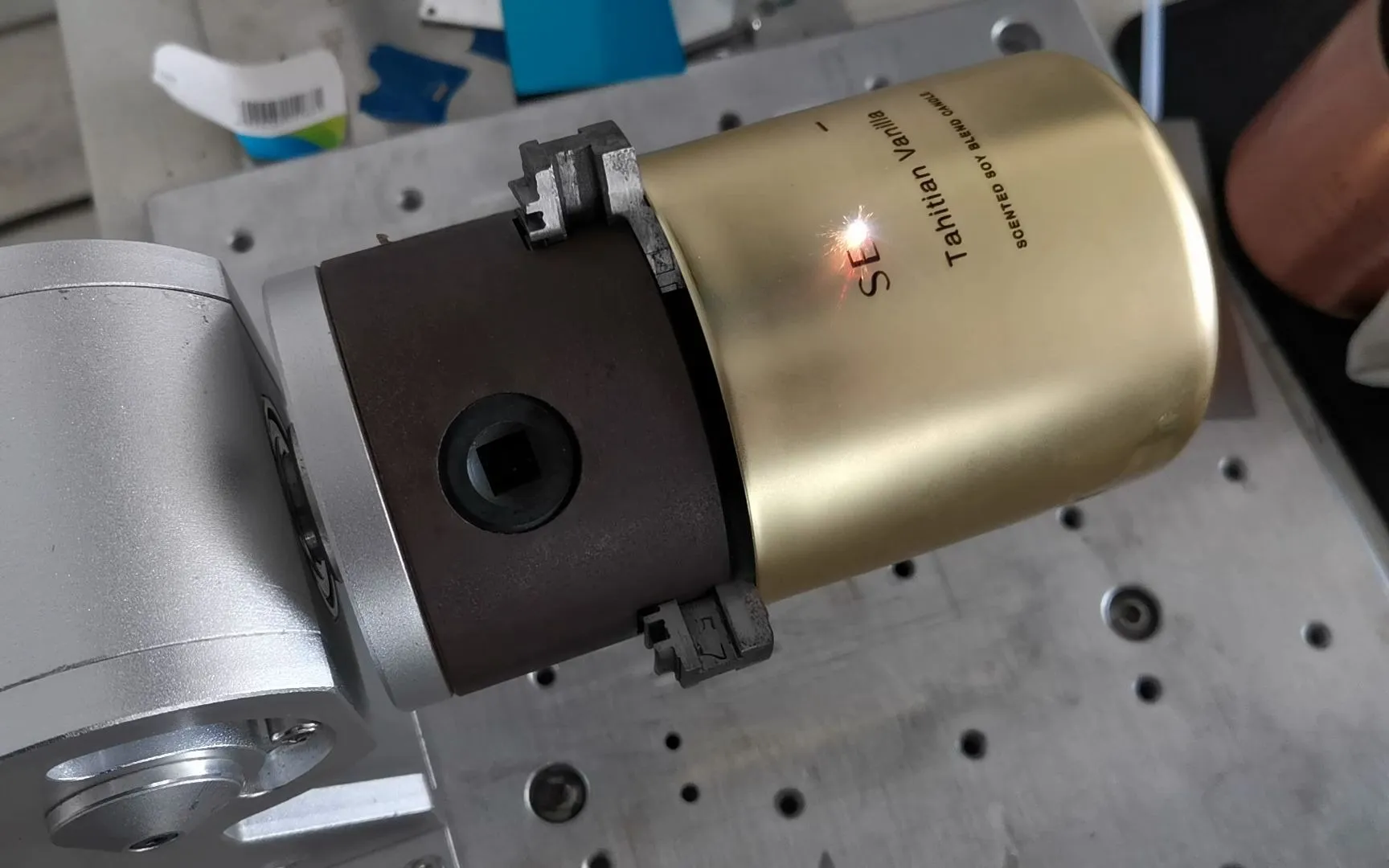
In a typical setup, the operator or automation system loads the part into a chuck, roller or custom fixture. The controller is configured for the part diameter and required artwork. During marking, the rotary axis turns the workpiece while the laser scans the design. The actual motion sequence depends on the controller, rotary attachment, software and marking method.
There is one detail worth getting right before buying: a rotary axis does not physically make the entire surface flat. It helps present the curved surface to the laser in a controlled sequence. If the workpiece wobbles, the diameter is entered incorrectly, or the surface moves outside the usable focus range, the mark can still distort or become uneven.
What the Rotary Axis Actually Controls
- Angular movement: rotates the part to bring different surface positions into the marking path.
- Workpiece holding: keeps the part secured while the laser is operating.
- Position repeatability: helps return the part to a known angular position when the fixture and setup are consistent.
- Artwork mapping: coordinates the programmed design with the workpiece rotation, subject to the controller and software configuration.
For simple logos or short text, setup is usually more straightforward than for a dense QR code, a long design that wraps around a cylinder, or a ring that needs marking on its inner wall. Those applications need closer attention to fixture geometry, focus and artwork layout.
What Can You Mark with a Rotary Axis?
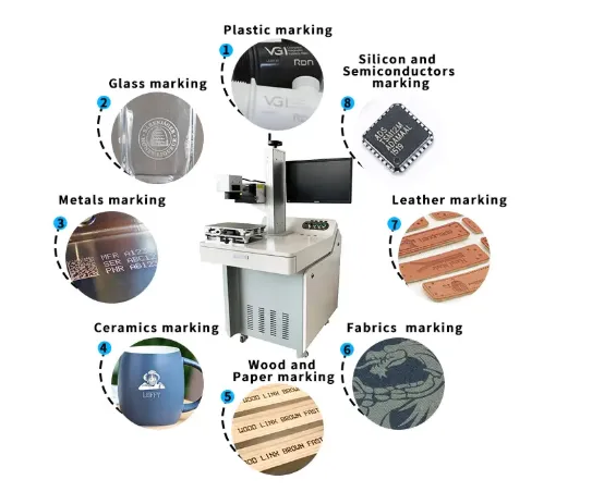
Rotary laser marking is useful when the identification area follows a circular or cylindrical surface. The following examples show where it can work and what should be checked before selecting a machine.
Metal Rings and Jewelry
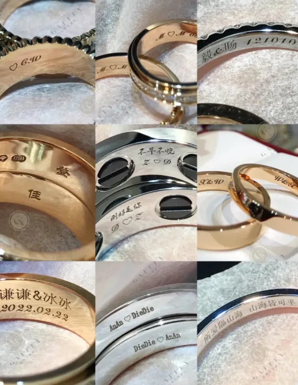
Logos, names, dates, short text and selected serial information on ring surfaces. The fixture must hold the ring securely without damaging a finished surface. Inner-wall marking may need a specialized holder and optical access.
Shafts and Pins
Part numbers, batch IDs and serial numbers on steel or stainless-steel shafts, pins and round mechanical parts. Long parts may need tail support to reduce movement during rotation.
Bearings and Sleeves
Identification on suitable bearing surfaces, sleeves and cylindrical components. Confirm that the chosen marking location is permitted and will not affect a precision fit, raceway or functional surface.
Tools and Hardware
Brand names, model information and product IDs on round tool bodies, sockets and selected hardware. A dedicated fixture can reduce manual alignment between repeated parts.
Tubes and Cylindrical Housings
Short text, logos and identification codes on suitable tubes and housings. Diameter, length, wall shape and the location of the mark determine whether a chuck, rollers or a custom support is appropriate.
Automotive and Industrial Parts
Traceability information on compatible round components, shafts, bushings and other metal parts. The production system may also require part detection, variable-data input and code verification.
Related application pages: Metal Parts Marking, Automotive Parts Marking and Jewelry Laser Marking. Confirm these destination URLs in WordPress before publishing.
Rotary Axis Machine Parameters: What Do the Numbers Mean?
The table below combines the reference specifications published on JQ Laser’s rotary-axis and automatic marking pages. These are reference configurations, not a guarantee that every laser source, lens and rotary attachment will deliver the same result.
| Parameter | Published Reference | What to Confirm Before Ordering |
|---|---|---|
| Fiber laser power | 20W / 30W / 50W / 60W / 100W options, depending on configuration | Material, required contrast or depth, artwork and target cycle time |
| Fiber wavelength | 1064 nm | Confirm the actual laser source and wavelength in the quotation |
| Reference scanning speed | Up to approximately 7,000 mm/s | Actual artwork, line spacing, rotary movement, number of passes and handling time |
| Typical marking field | 110 × 110 mm standard reference; other lens fields may be available | Lens, working distance, usable field and the location of the curved surface |
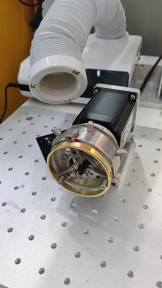
| Rotary mechanism | Motorized rotary chuck, roller or customized fixture | Diameter range, length, weight, runout, clamping and support |
| Positioning accuracy | Approximately ±0.01 mm reference on the product page | Ask what is measured, under which conditions, and whether this is rotary positioning, fixture repeatability or finished-mark accuracy |
| Control and software | Laser marking controller; EZCAD-compatible configuration depending on system | Rotary support, controller compatibility, data workflow and any PLC interface |
| Automation | Optional sensors, PLC / I/O and vision, subject to project scope | Trigger sequence, part detection, code verification and reject handling |
Important distinction: the 110 × 110 mm figure describes a typical optical marking field, not the maximum circumference that can be marked in one uninterrupted operation. The rotary axis changes the workpiece’s angular position; the usable layout depends on the controller, rotary setup and the specific marking task.
See the JQ Laser Rotary Axis Machine and Fiber Laser Marking Machine pages for the related product configurations.
Rotary Chuck vs. Roller vs. Custom Fixture
Choosing the right fixture often matters more than buying a higher-wattage laser. If a part slips or wobbles, a more powerful source will not fix the positioning problem.
| Fixture Type | Best Starting Point | Common Limitations | Questions to Ask |
|---|---|---|---|
| Rotary chuck | Rings, shafts, small cylindrical metal parts and components needing positive clamping | Jaw clearance, clamping marks, concentricity and access to the marking surface | What diameter and weight range can it hold? Is tail support needed? |
| Roller rotary | Suitable tubes, cylindrical containers and parts that can sit stably on rollers | Slip, uneven surfaces, taper and inconsistent contact | Will the surface remain synchronized with the rollers? Can the part drift sideways? |
| Expanding mandrel or dedicated ring holder | Ring-shaped parts that need internal or external positioning | Part variation, wall thickness, clamping pressure and optical access | Does the holder leave the intended mark area accessible and protect the finish? |
| Chuck with tail support | Long shafts, rods and slender cylindrical components | Part bending, alignment and support interference | Can both ends be supported without blocking the marking path? |
| Custom fixture | Irregular, tapered, delicate or multi-variant parts | Engineering cost, setup time and product changeover | How many variants must the fixture accommodate, and how is correct loading checked? |
How to Mark Rings: Outside, Inside and Side Surfaces
“Mark a ring” can mean several different jobs. The ring’s shape and the location of the mark determine the fixture and optical access needed. Do not assume a standard rotary chuck can handle all three cases.
1. Outside Surface of a Ring
For a logo or short text on the outer circumference, the ring must be held concentrically and rotated through the programmed marking path. Check that the ring does not tilt or shift when clamped. If the ring has a polished or coated finish, use a holding method that protects the visible surface.
2. Inside Wall of a Ring
Internal ring marking is more demanding. The laser needs a clear line of sight to the inside wall, and the ring holder must leave the target area accessible. Depending on the ring diameter and inner-wall geometry, a special mandrel, angled fixture or different optical arrangement may be required. A conventional rotary attachment alone does not guarantee that the inside wall can be reached.
Before ordering, send the ring’s inner diameter, outer diameter, width, material, wall shape and the exact position of the mark. A physical sample is strongly recommended.
3. Flat Side or End Face of a Ring
If the mark belongs on a flat side face or end face, a rotary axis may not be needed for the marking itself. A fixed fixture may be simpler and less expensive. A rotary mechanism becomes useful if the part must be indexed to different angular positions or if the same setup also marks a curved surface.
How to Mark Cylindrical Metal Parts Without Distortion
For shafts, sleeves, tubes and cylindrical housings, the main issues are usually surface runout, focus variation, diameter entry and artwork mapping. The process should be checked in this order.
- Measure the actual diameter. Use the diameter at the marking location, not just a nominal drawing value if the part has taper, coating or machining variation.
- Check concentricity and runout. Rotate the clamped part and observe whether the surface moves noticeably relative to the laser’s focal position.
- Set the working height. Establish focus at the intended mark area. A large diameter change or an off-center fixture can shift the surface away from the useful focus range.
- Check the rotary setup. Confirm the software and controller use the correct rotary configuration and that the intended rotation direction and scale are correct.
- Test a short mark first. Begin with a small logo or short text to check direction, scale, position and seam behavior before running a full wraparound design.
- Inspect the actual result. Check dimensions, legibility, seam alignment and consistency at multiple angular positions.
- Repeat the test. Mark several parts after unloading and reloading. A good first sample does not prove that the fixture is repeatable in production.
If the text is stretched, the first step is to check the entered diameter and rotary mapping. If one side is sharp and the other side is weak, check focus, runout and surface geometry. If the mark starts and ends at different positions, check the artwork, rotary calibration and seam setup. These checks are more useful than changing laser power at random.
Realistic Workpiece Examples and Selection Guidance
The table below gives practical starting points for discussing a project. It is not a list of guaranteed processing results; material grade, surface finish and acceptance criteria must still be tested.
| Workpiece Example | Likely Marking Need | Fixture Starting Point | Key Test |
|---|---|---|---|
| Stainless-steel shaft | Part number, serial number or logo | Chuck; tail support for long parts if needed | Runout, focus and mark readability |
| Aluminum sleeve or housing | Logo, batch ID or traceability code | Chuck or custom nest | Surface finish, contrast and dimensional variation |
| Small metal ring | Short text, logo or serial information | Ring holder or suitable chuck | Clamping marks, centering and optical access |
| Bearing sleeve | Identification on an approved non-functional area | Dedicated fixture based on geometry | Avoiding functional surfaces and confirming code readability |
| Brass or copper cylindrical part | Logo, model ID or production code | Chuck or custom fixture | Reflectivity, surface condition and contrast |
| Long steel tube | Text or ID at a defined position | Roller or supported rotary arrangement, depending on size | Slip, sag, lateral movement and marking location |
For metal applications, start by reviewing the Fiber Laser Marking Machine. For selected stainless-steel appearance requirements or applications that benefit from adjustable pulse duration, compare the MOPA Laser Marking Machine. Choose the source only after testing the actual workpiece.
Can a Rotary Axis Mark a Full 360° Circumference?
It can be configured for circumferential marking, but “360° marking” needs to be defined carefully. A full circumference may mean a small logo placed at a chosen angular position, multiple separate marks around the part, or one continuous design that wraps around the entire surface. These are different jobs.
For a continuous wraparound design, check the seam between the start and end of the artwork, the usable surface length, the actual diameter and the controller’s rotary mapping. For separate marks at fixed angles, the system needs reliable angular positioning and a way to index the part. If the part is tapered or not truly round, the mark can change in focus or scale as the surface rotates.
Before accepting a machine, define whether the requirement is a partial arc, a full wraparound logo, several indexed positions or continuous variable data. Ask the supplier to demonstrate that exact operation using your part.
How Much Does a Rotary Laser Marking Machine Cost?
The cost depends on more than the laser power. The rotary mechanism, fixture design, laser source, marking lens, enclosure, controller, automation and shipping terms all affect the final quotation.
| Configuration | Cost Drivers | What to Clarify |
|---|---|---|
| Standard marking machine with rotary attachment | Laser source, power, lens, rotary type and standard accessories | Included fixture, diameter range, software support and installation scope |
| Custom ring or cylindrical-part fixture | Part geometry, material protection, clamping and changeover needs | Number of product variants, repeatability target and spare fixture parts |
| Automated rotary station | PLC, sensors, vision, enclosure, feeding and custom integration | Cycle time, interface responsibilities, acceptance test and service requirements |
JQ Laser’s public product listings show an indicative budget range of USD 2,000–4,500 for certain standard machine configurations, but this should not be treated as a fixed quotation for every rotary project. Confirm the exact rotary hardware, fixture, enclosure, automation scope and shipping terms before comparing suppliers.
A useful purchasing comparison should list the same deliverables on every quote: laser source and rated power, marking field, rotary type, supported workpiece dimensions, fixture, controller and software, safety enclosure, sample test, warranty, spare parts, training and delivery terms.
How to Calculate Whether a Rotary Axis Is Worth Buying
A rotary axis can reduce repeated manual repositioning, but it also adds setup, loading and maintenance requirements. Whether it improves output depends on the current bottleneck.
Measure the existing process first:
- Time needed to load and align one part.
- Time spent rotating or repositioning the part manually.
- Laser marking time per position.
- Time needed for inspection and unloading.
- Rework caused by incorrect position or inconsistent marks.
Then compare the complete cycle using a rotary fixture, not just the laser’s scanning time. If the operator spends most of the cycle loading a heavy part, the rotary axis alone may not solve the bottleneck. If repeated angular positioning is the main delay, a well-designed rotary fixture may be more valuable.
For higher-volume projects, evaluate whether a sensor, PLC trigger, custom nest or automated loading system is justified. See our Automatic Laser Marking Machine and Automation Marking Solution pages.
Sample Testing: What Should the Supplier Prove?
For rings and cylindrical parts, a photo of a good-looking flat sample is not enough. The supplier should test the actual workpiece on the proposed rotary setup whenever possible.
Recommended Sample-Test Procedure
- Record the part: note material grade, surface treatment, diameter, length, weight and mark location.
- Confirm the fixture: document the chuck, roller, mandrel or custom holder used.
- Set up the rotary axis: record the relevant diameter entry, rotation direction, controller configuration and focus position.
- Mark the actual artwork: use the customer’s logo, text, serial number or 2D code rather than a generic demonstration pattern alone.
- Check geometry: inspect text scale, distortion, position, seam alignment and angular repeatability.
- Check mark quality: evaluate contrast, readability, depth if required, surface damage and any functional restrictions.
- Repeat the process: unload and reload several samples to check whether the result is repeatable.
- Document acceptance: save sample photos, configuration, parameters, inspection method and customer-approved criteria.
For a QR code or Data Matrix, use the customer’s intended reader or verifier when available. A code that looks readable to the eye may still fail a production reader. If the part will be coated, cleaned, exposed to chemicals or subjected to wear, include the relevant downstream validation in the approval plan.
Factory Capability, OEM, Lead Time and Quality Control
For an industrial rotary project, the supplier needs to demonstrate more than a working laser source. The rotary attachment, fixture, control setup and safety functions must work together as a complete system.
Manufacturing and Configuration
Jining Junqi Intelligent Technology Co., Ltd. (JQ Laser) supplies laser marking equipment and can evaluate configurations for rings, shafts and other cylindrical components. Depending on the application, the project can be reviewed for laser source, marking lens, rotary chuck or roller, dedicated fixture, enclosure and optional automation.
OEM and Customized Fixtures
OEM/ODM or customized configuration should be defined in writing. Provide the part drawing, marking location, dimensions, material and any product-changeover requirements. Confirm whether the quotation includes custom fixture design, fixture manufacture, software configuration, electrical integration, documentation and sample acceptance.
Learn more about OEM & ODM Services.
MOQ and Production Lead Time
For a standard machine, a one-unit order may be possible, subject to confirmation of the exact configuration and order terms. Custom rotary fixtures or automated stations may require additional engineering and testing. A typical standard fiber machine production reference is 5–7 working days, but this is not a guaranteed lead time for customized rotary or automation projects. Confirm the production schedule after the technical scope is approved.
Quality Control Before Shipment
For a rotary configuration, ask the supplier to document the checks relevant to the ordered machine, such as laser operation, sample-mark quality, rotary movement, fixture alignment, software operation, external trigger or PLC sequence when included, and applicable safety functions. If your process needs a specific repeatability or code-readability threshold, put the test method and acceptance criteria in the purchase specification.
Spare Parts and After-Sales Support
Before ordering, confirm the warranty terms, support channel, controller and laser-source model, rotary motor or drive details, fixture components and the availability of replacement parts. For production use, keep the approved marking files and parameter records backed up. Ask which components are considered routine spares and which repairs require a trained technician.
Related resources: Shipping & Delivery, After-Sales Support and Service & Support.
What to Send When Requesting a Rotary Axis Quotation
These details help avoid a quotation that looks inexpensive but does not fit the actual part.
- Part photos or drawings, including the exact marking surface.
- Material grade and surface finish.
- Minimum and maximum outer diameter; for rings, also inner diameter and width.
- Part length and weight; indicate whether the part is tapered, hollow or irregular.
- Marking content, artwork file, code type and required mark dimensions.
- Whether you need outer-surface, inner-wall, end-face, partial-arc or full-circumference marking.
- Required production cycle time and expected daily or monthly quantity.
- Manual, semi-automatic or inline production method.
- Required inspection method, acceptance criteria and destination country.
With this information, the supplier can assess the rotary mechanism, laser source, lens, fixture and any automation requirements before preparing a final quotation.
Frequently Asked Questions
How does a rotary axis mark a cylindrical metal part?
The rotary axis turns the workpiece in a controlled way while the laser marks the exposed surface. The controller coordinates the artwork with the rotary movement. Correct diameter setup, stable clamping, focus and rotary calibration are important for avoiding distortion.
Can a rotary laser mark the full 360° circumference?
Yes, a suitable system can be configured for full-circumference marking. The design must account for the actual diameter, rotary mapping, usable focus range and start-to-end seam. Continuous artwork and separate indexed marks should be treated as different requirements.
Can a standard rotary axis mark the inside of a ring?
Not necessarily. Inner-wall marking depends on the ring geometry, fixture, optical access and working distance. A dedicated holder or different optical arrangement may be needed. Confirm the inner diameter, ring width and mark location, and test the actual ring before ordering.
Which is better for cylindrical parts: a chuck or roller rotary?
A chuck is a useful starting point for parts that need positive clamping, such as many shafts and rings. A roller rotary can suit compatible tubes and cylindrical products that sit stably on rollers. Part shape, diameter, weight, surface finish and slip risk determine the better option.
What laser power do I need for rings and metal cylinders?
Power depends on the material, mark size, required contrast or depth and target cycle time. JQ Laser lists fiber configurations from 20W to 100W for different applications. A 20W or 30W machine may be adequate for many identification marks, while demanding depth or throughput requirements may justify a different configuration. Test the actual part before selecting power.
Why does rotary text sometimes look stretched or distorted?
Common causes include an incorrect diameter setting, rotary mapping or calibration errors, slippage, runout, a tapered part or focus variation. Check the geometry and setup first rather than changing laser power at random.
Can I mark QR codes or Data Matrix codes on cylindrical parts?
Yes, if the code dimensions, curvature, contrast and marking process allow it. Validate the code using the intended reader or verifier. Dense codes on small diameters need particular attention to module size, distortion and focus.
Can the rotary axis be integrated with a PLC or production line?
PLC, sensor and I/O integration may be included depending on the project. Confirm the trigger sequence, part detection, variable-data input, completion signal, fault handling and any code verification or reject-handling requirements before ordering.
What should I test before accepting a rotary marking machine?
Use the actual workpiece and artwork. Check mark quality, scale, position, seam alignment, focus, repeatability after reloading and any required code readability. Document the configuration and acceptance criteria so the sample test can be traced to the delivered machine.
Need a Rotary Axis for Rings or Cylindrical Metal Parts?
Send JQ Laser the part dimensions, material, marking location and artwork. We can evaluate whether a rotary chuck, roller or custom fixture is appropriate and which laser configuration should be tested.
For production applications, include your cycle-time target and inspection requirements. This helps us discuss the complete process rather than quoting a rotary attachment that may not suit your workpiece.
Related Resources
Technical Notes and Verification
The power, wavelength, marking field, scanning speed and positioning figures in this article are reference specifications taken from JQ Laser’s published rotary-axis and automatic laser marking pages. The final machine configuration and test results should be recorded in the quotation and sample-acceptance documents.
For each production application, keep a traceable record of the part drawing or sample ID, material and surface condition, rotary fixture, lens and laser configuration, approved marking file, parameter set, sample photos, inspection method, acceptance result and machine serial number. This is a practical way to link the approved sample to the delivered system and later troubleshooting.
Technical references: JQ Laser Rotary Axis Specifications; JQ Laser Automatic Marking Specifications; JQ Laser Installation, Training and Sample Testing.