Choosing a conveyor laser marking machine is not just about adding a belt to a fiber laser. The real job is to make sure every product reaches the correct marking position, receives the correct information, and leaves the station with a readable and consistent mark without slowing down the production line.
For some factories, a sensor-triggered conveyor with stop-and-mark operation is enough. For faster lines, a flying laser marking system with encoder synchronization may be the better option. The right choice depends on your product, line speed, marking content, product spacing and quality requirements.
Quick Answer: Which Conveyor Laser Marking System Should You Choose?
If your products can pause briefly at the marking station, start by evaluating an indexed conveyor system. It is usually easier to position, program and troubleshoot. If your conveyor must keep moving, evaluate a mark-on-the-fly system with an encoder and a controller designed to compensate for product movement.
| Your production situation | Recommended configuration | What to confirm before ordering |
|---|---|---|
| Products can stop at the marking station | Conveyor + photoelectric sensor + stop-and-mark control | Positioning repeatability, stopping time and fixture design |
| Products must keep moving | Flying marking + encoder + product trigger | Conveyor speed range, encoder resolution and synchronization accuracy |
| Products have different positions or orientations | Conveyor + vision positioning + suitable fixture | Camera field of view, lighting, image processing and actual positioning tolerance |
| Every product needs a unique serial number or code | Laser controller + PLC or data interface + variable-data software | Data source, communication protocol, duplicate prevention and code verification |
| Defective marks must not reach the next process | Marking + code inspection + reject or alarm mechanism | Inspection criteria, reject timing and failure-handling logic |
One point worth remembering: a laser scanner advertised at 7,000 mm/s does not mean your production line can process products at a corresponding rate. Actual output depends on the marking file, material, laser settings, product spacing, trigger delay, conveyor movement, handling time and inspection process.
1. What Is a Fiber Laser Marking Machine with a Conveyor?
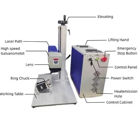
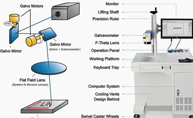
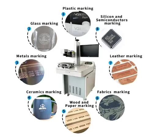
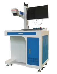
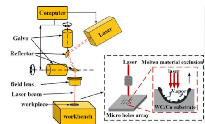
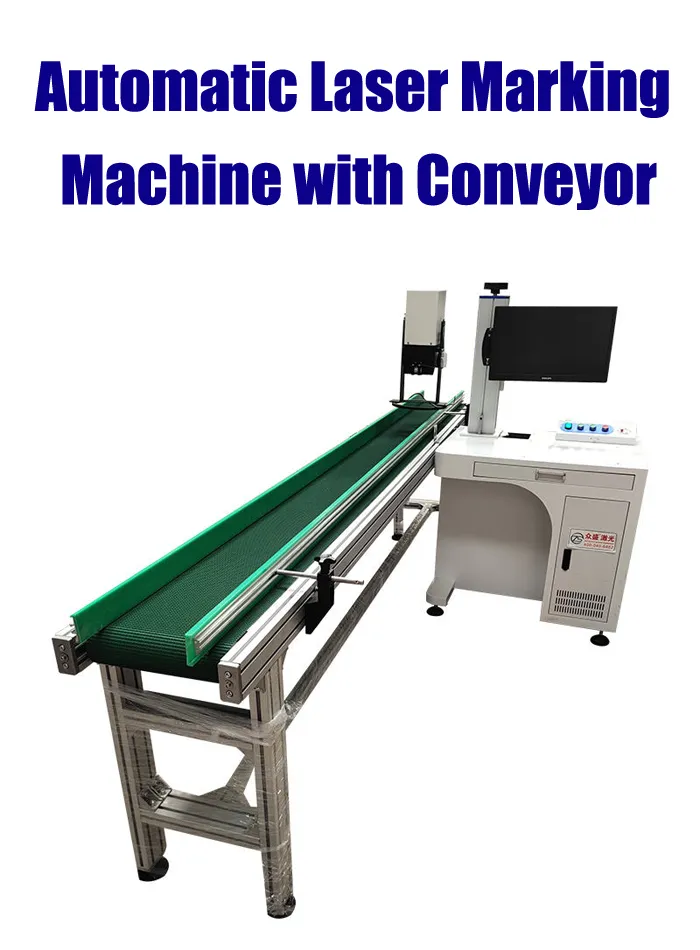
A fiber laser marking machine with a conveyor combines a laser marking head, laser source, control system and material-handling conveyor. Products travel through a defined marking area, where the system applies information such as serial numbers, QR codes, Data Matrix codes, barcodes, logos, batch numbers or production dates.
Unlike a conventional desktop marking machine, the conveyor configuration is designed around the production flow. The operator does not need to place every part manually under the laser. Depending on the system design, the product can stop for marking or be marked while it is moving.
Two different ways to mark products on a conveyor
A. Stop-and-Mark Conveyor System
The photoelectric sensor detects an incoming product. The conveyor stops or the product is positioned by a stopper or fixture. The laser marks the product after the position is confirmed. Once marking is complete, the conveyor moves the product to the next station.
- Suitable for products that need stable positioning.
- Useful when the marking content is relatively large or requires multiple passes.
- Often easier to commission than a fully dynamic flying system.
- The stopping and restarting cycle must be included in the production takt time.
B. Flying Laser Marking System (Mark-on-the-Fly)
In a flying marking system, the product continues moving while the laser marks it. A photoelectric sensor detects the product, while an encoder measures conveyor movement. The controller uses the movement information to synchronize the marking process with the product’s position.
- Suitable for production lines that cannot stop for marking.
- Useful for date codes, serial numbers, QR codes and compact product identification.
- Requires reliable synchronization between the conveyor, encoder and laser controller.
- Product movement, spacing variation and speed fluctuation must be tested under real production conditions.
These two configurations should not be treated as the same machine with different software settings. Their mechanical design, triggering logic, motion control and commissioning requirements can be different.
2. How a Continuous Conveyor Laser Marking System Works
A typical inline marking process follows this sequence:
- Product feeding: Products enter the conveyor manually or through an automatic feeding system.
- Product detection: A photoelectric sensor detects the product approaching the marking station.
- Position or movement measurement: The system either stops and positions the product or reads conveyor movement through an encoder.
- Data preparation: The marking controller receives fixed or variable information, such as a serial number or production code.
- Laser marking: The laser applies the required text, logo or code.
- Quality inspection: An operator or vision system checks the mark. Where required, a barcode or Data Matrix reader verifies code readability.
- Product release: The product continues to the next process. A reject mechanism can remove products that fail inspection if the system is designed for it.
For a simple installation, the sensor may only need to trigger the laser. A more advanced production line may also need encoder feedback, PLC communication, unique data management, code verification and automatic rejection.
Do not assume that all these functions are included in the basic conveyor price. Ask the supplier to list which components and functions are included, optional or supplied by your factory.
3. Real Production Applications: Where Does a Conveyor Fiber Laser Make Sense?
3.1 Automotive Metal Components
Automotive suppliers often need permanent identification on metal components. Examples include brackets, machined parts, housings, fasteners, tooling components and selected engine or transmission parts.
A conveyor system can move components through a marking station to apply part numbers, serial numbers, supplier codes or 2D identification codes.
Typical configuration to evaluate: 30W or 50W fiber laser, conveyor with a repeatable product guide, sensor trigger, and a fixture if the part has an irregular surface. For unique part identification, add a data interface and code verification.
Important limitation: automotive traceability requirements vary by customer and component. A mark that looks clear to the eye may still fail a customer’s code-quality requirement. Test the actual code using the required verification method and specification.
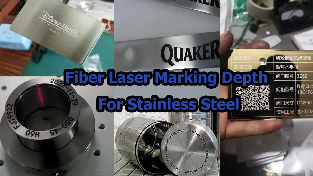
3.2 Stainless Steel Parts and Metal Fabrication
Metal fabrication factories may need to mark stainless steel plates, metal fittings, machine parts, tools, enclosures and hardware products in batches.
A conveyor can reduce manual loading and unloading when the parts have consistent dimensions and can travel in a stable orientation.
Typical configuration to evaluate: 20W or 30W fiber laser for many identification tasks. Consider 50W when deeper engraving, a larger marking workload or a shorter cycle time is required. The correct power still needs to be confirmed by sample testing.
Important limitation: stainless steel surface finish, coating, oxidation, part geometry and required contrast can change the marking result. A polished part and a brushed part may not produce the same appearance with identical parameters.
3.3 Electronic Components and Electrical Products
Electronic manufacturers may mark metal connectors, housings, heat sinks, electrical enclosures and selected components with model numbers, logos, serial numbers or 2D codes.
For small components, the main challenge is often not laser power. It is consistent positioning and ensuring that the marking field covers the required area without hitting the wrong surface.
Typical configuration to evaluate: 20W or 30W fiber laser, a suitable small-field lens, product guides or nests, and vision positioning when product location varies.
Important limitation: many electronic products contain plastics, coatings or heat-sensitive materials. A 1064 nm fiber laser is not automatically the right choice for every surface. Test the exact material and compare UV marking where heat-related damage is a concern.
3.4 Bearings, Fasteners and Standardized Small Parts
Bearings, bolts, nuts, metal fittings and other small parts are often produced in batches. A conveyor can help reduce repetitive manual placement and maintain a consistent flow.
Typical configuration to evaluate: 20W or 30W fiber laser, adjustable product guides, a sensor and a dedicated fixture where necessary. For parts that can roll or rotate, mechanical restraint is important.
Important limitation: a flat belt alone may not keep round or irregular products in the correct orientation. A guide rail, nest, stopper or custom feeding mechanism may be needed.
3.5 Packaging Lines and Product Identification
Some production lines need permanent codes or product information on metal packaging components, labels, coated metal surfaces or other compatible materials.
For packaging materials such as paper, cardboard, glass or certain plastics, a fiber laser should not be selected simply because it is available. CO2 or UV laser technology may be more suitable depending on the material and required result.
Important limitation: test the actual packaging material, coating, production speed and required contrast. Do not assume that one laser wavelength works equally well on all packaging materials.
4. JQ Laser Conveyor Marking Configuration and Reference Parameters
JQ Laser’s conveyor-based solution can be configured around fiber, MOPA fiber or UV laser technology, depending on the material and marking requirement. The conveyor, trigger method, PLC connection, fixtures and vision functions should be selected according to the customer’s production line.
Fiber Laser Reference Configuration
| Item | Reference configuration | What the buyer should confirm |
|---|---|---|
| Laser power | 20W, 30W, 50W, 60W and 100W options depending on configuration | Actual source model, rated output power and suitability for the material |
| Laser wavelength | 1064 nm for standard fiber laser configurations | Confirm the wavelength for the selected laser source |
| Standard marking field | 110 × 110 mm reference configuration | Actual lens field, working distance and usable marking area |
| Optional marking field | Other lens sizes can be configured | Confirm the available lens sizes and the effect on spot size and marking quality |
| Marking head | Galvanometer scanning head | Brand, model, scan field and repeatability |
| Conveyor | Customized to product dimensions and production layout | Belt width, length, load, speed range, guide rails and frame design |
| Product trigger | Photoelectric sensor or other suitable detection method | Sensor type, detection distance, response and product spacing |
| Encoder | Optional or required according to the motion-marking design | Encoder resolution, installation method and controller compatibility |
| Control | Laser marking controller; PLC integration according to project requirements | Signal list, communication protocol and responsibility for line integration |
| Vision system | Optional | Position correction, code inspection or both; these are different functions |
Parameter note: the values above describe reference configuration options, not a promise that every option is included in one standard machine. The final specification must identify the actual laser source, scanner, lens, conveyor, controller, sensor, encoder and software model.
Why We Do Not Publish One Fixed Conveyor Speed for Every Project
A conveyor speed in meters per minute does not tell the whole story. A line carrying small parts with short serial numbers is very different from a line carrying large housings with a long QR code and logo.
For example, a system may have a high-speed galvanometer scanner, but the actual line output can still be limited by:
- The time required to mark the complete content.
- The distance between products.
- The sensor detection and trigger delay.
- Conveyor speed variation or product movement.
- Product orientation and positioning accuracy.
- Loading, unloading and downstream inspection.
We recommend calculating the required cycle time from the real marking file and product flow, then confirming it with a production-style sample test.
5. Five Engineering Issues That Can Cause Problems on a Conveyor Marking Line
Problem 1: The Marking Position Changes from Product to Product
What happens: the mark appears too far to the left or right, or its position changes between products.
Common reasons: inconsistent product spacing, parts entering at different angles, belt vibration, loose guide rails or an unstable product surface.
Practical solution:
- Use adjustable guide rails to control the product path.
- Add a stopper or dedicated fixture for products that need accurate positioning.
- Use a vision system if product position or orientation cannot be controlled mechanically.
- Test the position at the beginning, middle and end of a production run.
Do not use a camera to solve a mechanical problem that can be fixed with a simple guide rail. Mechanical positioning is often the simpler and more economical first step.
Problem 2: The Mark Becomes Stretched or Compressed on a Moving Product
What happens: characters, logos or codes appear distorted when the conveyor is running.
Common reasons: the marking controller is not synchronized with conveyor movement, encoder settings are incorrect, or conveyor speed changes during marking.
Practical solution:
- Confirm whether the application needs stop-and-mark or flying marking.
- For flying marking, use a suitable encoder and confirm that the controller supports the required motion compensation.
- Check encoder direction, pulse settings, wheel contact and mechanical slip.
- Run tests at the minimum, normal and maximum expected conveyor speeds.
A sensor tells the system when a product arrives. An encoder measures movement. They do different jobs, and one should not be assumed to replace the other in a dynamic marking application.
Problem 3: The Laser Marks the Wrong Product or Repeats a Serial Number
What happens: a serial number is assigned to the wrong part, a product is marked twice, or a code is skipped.
Common reasons: the data source and product trigger are not synchronized, communication is interrupted, or the system has no clear record of whether a product has already been marked.
Practical solution:
- Define where the serial number or variable data comes from.
- Agree on the data exchange method between the laser controller, PLC and factory system.
- Define what happens when a product is detected but the data is missing.
- Use product tracking or a controlled marking queue where each product requires unique information.
- Test communication interruptions, repeated triggers and product gaps.
For traceability applications, the supplier should explain how the system handles missing, repeated or delayed data. A successful demonstration with a fixed serial number does not prove that unique-code production is ready.
Problem 4: The Laser Can Mark Fast, but the Production Line Is Still Slow
What happens: the scanner finishes marking quickly, but products accumulate before or after the laser station.
Common reasons: loading, spacing, product orientation, stopping time, inspection or reject handling becomes the actual bottleneck.
Practical solution:
- Measure the complete time from one product entering the station to the next product being released.
- Record marking time separately from conveyor and handling time.
- Check whether the next process can accept products at the same rate.
- Consider automatic feeding or a second station only after identifying the real bottleneck.
Buying a 50W laser instead of a 30W laser will not solve a conveyor bottleneck if the main delay is manual loading or product positioning.
Problem 5: The Mark Looks Good, but the Code Cannot Be Read Reliably
What happens: a QR code or Data Matrix code looks acceptable to an operator but fails at the customer’s scanner or inspection station.
Common reasons: insufficient contrast, inconsistent module size, surface reflection, unsuitable code dimensions, contamination or distortion caused by product movement.
Practical solution:
- Use the actual code content and required physical dimensions during the sample test.
- Check the code using the reader or verification method required by the customer.
- Test different surface finishes and product orientations.
- Where required, add an inline code reader after the laser station.
- Define what happens when the code fails inspection.
Code readability and code quality grading are not the same thing. If your customer specifies a verification standard, include that standard in the purchase specification instead of relying on a visual sample alone.
6. How to Calculate Whether a Conveyor Laser Marking Machine Can Meet Your Production Rate
Before asking for a quotation, prepare the required output in parts per minute or parts per hour. The supplier needs to know more than the conveyor’s maximum speed.
Start with the required takt time
Takt time is the available production time divided by the required number of products. It tells you how much time the process can use for each product to meet demand.
Required takt time = Available production time ÷ Required output quantity
For example, assume a line needs to produce 1,200 parts in an eight-hour shift. If the full 28,800 seconds were available, the theoretical takt time would be:
28,800 seconds ÷ 1,200 parts = 24 seconds per part.
This is only a planning example. Real production time must account for breaks, changeovers, downtime and other scheduled losses.
Then calculate the marking station’s actual cycle time
For a stop-and-mark system, consider:
- Product arrival and detection.
- Conveyor stopping and positioning.
- Laser marking time.
- Any required inspection.
- Product release and conveyor restart.
For a flying marking system, consider:
- Product detection and trigger delay.
- Encoder synchronization.
- Actual marking time while the product is moving.
- Product spacing and the available marking window.
- Inspection and reject handling, if included.
Do not approve a machine based on a theoretical calculation alone. Ask the supplier to test your actual product, marking content and expected conveyor speed. Record the number of accepted products per minute, not just the scanner’s maximum speed.
7. How to Choose the Right Laser Power for Conveyor Marking
Higher laser power can improve processing capacity in some applications, but it is not a direct substitute for a well-designed conveyor and marking process.
| Laser power | Applications to evaluate | When it may be suitable | What still needs testing |
|---|---|---|---|
| 20W | Serial numbers, logos, QR codes and general identification on compatible metals | Moderate marking workload and smaller or simpler marking content | Contrast, code readability and cycle time |
| 30W | Batch marking, metal components and production lines with a higher marking workload | When 20W cannot meet the required cycle time or marking result | Actual improvement in accepted parts per minute |
| 50W | More demanding marking tasks, selected engraving applications and higher-volume work | When the sample test shows a meaningful benefit from additional power | Engraving depth, heat effect, surface finish and cycle time |
| 60W / 100W | Selected higher-throughput or more demanding metal processing applications | When the required process cannot be achieved economically with lower power | Marking quality, thermal impact, process stability and total system cost |
These are starting points for evaluating a configuration, not universal application limits. The best power depends on material, surface condition, marking depth, content, lens, pulse characteristics and the required cycle time.
When should you consider MOPA instead of a standard fiber source?
A MOPA fiber laser offers adjustable pulse-width control on compatible source models. This can be useful for selected stainless steel marking effects, color marking experiments and applications where pulse characteristics affect the surface result.
However, MOPA is not automatically better for every conveyor application. If your job is straightforward serial-number marking on metal and a conventional fiber source passes the sample test, paying extra for MOPA may not create a practical production benefit.
For heat-sensitive plastics, glass or certain electronic materials, compare UV laser marking rather than assuming that a higher-power fiber laser is the answer.
8. Conveyor and Automation Components You Should Specify
Conveyor Belt and Mechanical Structure
Confirm the usable belt width, total length, height, load capacity, speed adjustment range and mounting position of the laser head. If your parts have different sizes, ask whether the guide rails and support structure can be adjusted.
Photoelectric Sensor
The sensor detects product arrival. Its type and mounting position should match the product’s size, surface, color, reflectivity and spacing. Highly reflective or transparent products may require a different detection approach from ordinary opaque parts.
Encoder
An encoder measures conveyor movement. It is particularly important for flying marking because the system must compensate for product movement while the laser is working.
Confirm encoder resolution, mounting, wheel contact, direction, signal type and controller compatibility. A poorly mounted encoder can slip or measure movement incorrectly.
PLC and Communication
A PLC can coordinate the conveyor, sensor, laser trigger, machine status and other production equipment. Before ordering, agree on the actual signal list and communication method.
Do not accept a general statement such as “PLC compatible” as a complete integration specification. Ask for the input and output list, interface details and the division of responsibility between the laser supplier and the factory’s automation team.
Vision Positioning and Code Inspection
Vision positioning and code inspection solve different problems:
- Positioning camera: finds the product or marking location before the laser marks.
- Inspection camera or code reader: checks the result after marking.
A camera used for positioning does not automatically verify whether a QR code can be read. If both functions are required, specify them separately.
Fume Extraction and Laser Safety
Marking can produce smoke, particles or process by-products depending on the material and surface coating. Extraction should be designed around the actual material and process. The extraction inlet should be positioned close enough to capture emissions without interfering with product handling.
Laser safety must also be considered as part of the complete production line. Depending on the laser class, installation and local regulations, the system may require suitable guarding, interlocks, beam stops, warning indicators and access control. Do not operate an open laser marking station as though the conveyor alone makes it safe.
9. Procurement Checklist: What Should You Confirm Before Buying?
Use this checklist when comparing suppliers. A quotation should answer these questions clearly. If an item is not applicable to your production process, ask the supplier to explain why it is unnecessary.
| Purchase item | Applicable operating conditions | Evidence or test method | Limitations to understand |
|---|---|---|---|
| 1. Laser source and power | All applications where marking quality or cycle time depends on laser output | Request source brand, exact model, rated power and a sample test on the actual material | Rated power alone does not establish marking speed, contrast or depth |
| 2. Marking content and dimensions | All applications, especially QR codes, Data Matrix codes and long serial numbers | Send the actual artwork and data format; test the smallest characters and required code size | A larger marking field may affect spot size and achievable detail depending on the lens |
| 3. Conveyor dimensions and load | Products transported automatically through the marking station | Provide product length, width, height, weight and a drawing; run loaded conveyor tests | A conveyor sized for one product may not suit a different product family or unstable load |
| 4. Stop-and-mark or flying marking | Stop-and-mark for products that can pause; flying marking for lines that must keep moving | Demonstrate the complete process at the expected production rate | Flying marking requires suitable motion synchronization; stop-and-mark adds stopping and restarting time |
| 5. Sensor and trigger logic | Applications where product arrival initiates marking | Test minimum and maximum product spacing, missed detections and repeated triggers | Sensor performance depends on product shape, surface, color, reflectivity and mounting |
| 6. Encoder and speed synchronization | Normally applicable to flying marking and other motion-synchronized processes | Record encoder resolution, mounting method and mark dimensions at several conveyor speeds | Encoder slip, incorrect scaling or unsuitable controller support can cause distortion |
| 7. PLC and data integration | Lines that exchange product information, status or commands with other equipment | Review the I/O list, communication protocol and test missing, delayed and duplicate data | Compatibility depends on the actual PLC, controller, software and integration scope |
| 8. Vision and code inspection | Products with variable positions or applications requiring automatic quality checks | Test positioning correction separately from post-marking code readability verification | Vision cannot guarantee performance under every lighting, surface or code condition |
| 9. Safety and fume extraction | All installations where laser exposure or process emissions need control | Review guarding, interlocks, emergency stops, extraction layout and applicable local requirements | Safety requirements depend on laser classification, installation design, material and jurisdiction |
| 10. Acceptance test and after-sales support | All production systems, especially customized or PLC-integrated lines | Agree on acceptance criteria, sample records, training, spare parts and remote support process | A factory sample demonstration may not reproduce every condition of the customer’s production line |
What to Put in the Purchase Agreement
For a conveyor laser marking system, the purchase agreement should not only state the laser power and machine model. It should also record:
- Material, product dimensions and product weight.
- Marking content, location and required physical dimensions.
- Required production output and operating speed range.
- Stop-and-mark or flying marking method.
- Sensor, encoder, PLC and data communication scope.
- Code readability or verification requirements, if applicable.
- Safety guarding and fume extraction responsibilities.
- Acceptance test method and pass/fail criteria.
- Installation, training, warranty and technical support scope.
10. Conveyor Laser Marking System Comparison
The following comparison helps distinguish a basic conveyor machine from a more complete inline marking solution.
| Configuration | How it works | Main advantage | Best suited to | Main limitation |
|---|---|---|---|---|
| Manual loading + desktop marker | Operator places each product under the laser | Simple setup and flexible for different products | Low-volume production and frequent product changes | Labor and manual handling limit throughput |
| Conveyor with stop-and-mark | Product stops at the marking station before marking | Stable positioning and relatively straightforward control | Batch production with products that can pause | Stopping and restarting adds cycle time |
| Flying laser marking | Laser marks while the conveyor continues moving | No need to stop the product for marking | Continuous production lines with suitable motion control | Requires reliable synchronization and a validated speed range |
| Conveyor + vision positioning | Camera identifies product position before marking | Can compensate for certain position or orientation variations | Products with variable placement | Requires suitable lighting, camera setup and image processing |
| Integrated marking and inspection line | Marks products, checks the result and may reject failed parts | Supports more complete production quality control | Traceability-sensitive or high-volume manufacturing | Higher integration cost and more commissioning work |
What Is the Difference Between a Conveyor Machine and a Complete Inline System?
A conveyor machine mainly transports products through the marking area. A complete inline system also considers how products are detected, positioned, identified, marked, inspected and released.
If your factory only needs to reduce manual handling, a basic conveyor may be enough. If your production line requires unique serial numbers, traceability records, code verification and automatic rejection, you should specify those functions as part of the automation project.
11. How JQ Laser Confirms a Conveyor Marking Project
We do not recommend choosing a conveyor system from a product photo alone. Before confirming the configuration, we need to understand how the product moves and what the laser must achieve.
Step 1: Check the Product
We need the actual material, surface condition, dimensions, weight and marking location. If one production line handles several product types, provide the range rather than only the smallest sample.
Step 2: Check the Marking Requirement
Send the logo, serial number, QR code or other marking content. Tell us whether the requirement is a visible identification mark, a deeper engraving result or a code that must pass a specific reader or verification standard.
Step 3: Check the Production Line
We need the conveyor speed, product spacing, required output, line height and available installation space. If the conveyor already exists, provide a layout drawing or a short video showing the product movement.
Step 4: Select the Laser and Automation Configuration
Based on the sample and line information, we can evaluate fiber, MOPA or UV laser technology, laser power, lens, conveyor structure, trigger method, encoder, PLC interface and optional vision functions.
Step 5: Test Before Finalizing the Specification
The sample test should use the actual material and marking content. For a continuous line, the test should also consider product movement, spacing and the expected production speed. Record the settings and results so the final configuration can be traced back to the tested conditions.
Step 6: Confirm the Scope and Acceptance Criteria
Before production, agree on which components are supplied by JQ Laser and which are provided by the customer. Define the acceptance test, required output, mark quality, data functions, safety requirements and support arrangements.
Our recommendation: if you are not sure whether you need a stop-and-mark conveyor or a flying laser system, send us your product and production-line details first. It is better to confirm the process before selecting the machine.
12. Frequently Asked Questions
Can a fiber laser marking machine mark products while they are moving on a conveyor?
Yes. A suitable flying marking system can mark products while the conveyor is moving. It normally needs a product trigger and encoder feedback, together with a controller that supports motion synchronization. The actual speed range must be tested with the required marking content.
Does every conveyor laser marking machine need an encoder?
No. A stop-and-mark system may use a sensor and a positioning mechanism without requiring conveyor-motion compensation. A flying marking application generally needs an encoder or another suitable method to measure movement and synchronize marking.
Can a conveyor laser marking machine mark unique serial numbers?
Yes, if the marking software and control system can receive and process variable data. For production traceability, confirm the data source, communication method, product-to-code assignment, duplicate prevention and error handling before ordering.
Can the machine connect to an existing production line PLC?
It can be designed for PLC integration, but the exact interface depends on the PLC, laser controller and required functions. Prepare the PLC model, signal list and communication requirements so the supplier can confirm compatibility.
Can a camera automatically position products before marking?
Yes. A vision positioning system can identify the product or marking location and correct certain placement variations. Its performance depends on the camera, lens, lighting, product surface, image processing and allowed positioning range. Test the real product rather than relying on a camera specification alone.
Can the system inspect QR codes after marking?
Yes, with a suitable inspection camera or code reader. However, positioning vision and post-marking code inspection are separate functions. Specify whether you need the camera to locate the product, verify code readability, grade code quality or perform more than one of these tasks.
Is 20W enough for a conveyor fiber laser marking machine?
It may be enough for many identification tasks, including serial numbers and selected QR codes on compatible metals. Whether it meets your production rate depends on the marking content, material, contrast, product spacing and cycle time. Test 20W against 30W or higher power using the same production conditions before deciding.
Is a 30W laser always faster than a 20W laser?
Not necessarily. A 30W source has higher rated average power, but the improvement in accepted products per minute depends on the marking process and the rest of the production line. If loading, positioning or inspection is the bottleneck, a higher-power laser may not improve total output significantly.
Can a fiber laser mark plastic products on a conveyor?
Some plastics and coatings can be marked with fiber lasers, but the result varies with material composition, color and additives. For heat-sensitive plastics, UV laser marking may be more suitable. Always test the exact material and confirm that the mark meets the appearance and readability requirements.
What information should I send to get a conveyor laser marking quotation?
Send product photos or samples, material, dimensions, weight, marking content, marking position, required output per minute, conveyor speed, product spacing and any PLC or inspection requirements. A short production-line video or layout drawing is also helpful.
13. Request a Conveyor Laser Marking Solution from JQ Laser
Are you planning to add laser marking to an existing conveyor or build a new automatic production line?
Tell us what you manufacture and how your products move through the line. We can help evaluate the laser type, power, marking field, conveyor structure, sensor, encoder, PLC interface and optional vision functions based on your actual application.
To help us evaluate your project, please prepare:
- Product photos or a sample.
- Material and surface finish.
- Marking content and marking position.
- Product dimensions and weight.
- Required output in parts per minute or hour.
- Conveyor speed and product spacing, if available.
- Existing PLC model and communication requirements.
- Whether you need flying marking, vision positioning or code inspection.
Contact JQ Laser for a Conveyor Laser Marking Solution
You can also review our automatic laser marking machines, fiber laser marking machines and laser marking automation solutions.
Technical References and Further Reading
The following references provide examples of conveyor marking configurations, industrial integration components and published equipment specifications. They are useful for understanding system architecture, but they do not replace testing on your own products and production line.
- JQ Laser: Automatic Laser Marking Machine with Conveyor – JQ Laser’s conveyor configuration options and application requirements.
- JQ Laser: Automatic Laser Marking Machine – Automation options and laser marking system configurations.
- Laserax: Automated Conveyor Laser Marking Machine – An industrial conveyor marking system and its published technical specifications.
- Laserax: Automatic Conveyor Machine Product Sheet – Published information on power options, communications and industrial integration.
- Luxinar: MULTISCAN HE User Manual – Describes conveyor-type installation components including product detection, shaft encoder, guarding and fume extraction.
- Videojet: Full Laser Marking System Solution – Illustrates the integration of product detection, encoder, beam shielding and fume extraction.
- WISELY: CCD & Conveyor Auto Laser Marker – Example of a conveyor and vision-assisted fiber laser configuration with published model parameters.