SMALL METAL PARTS BUYING GUIDE
For most small metal parts, a 20W or 30W fiber laser is a sensible starting point for logos, serial numbers, batch IDs and 2D codes. But wattage alone will not tell you whether a machine can mark your part clearly and repeatably. Before ordering, check the actual alloy and surface finish, the smallest feature you need to mark, how the part will be held, the required cycle time, and how the result will be inspected. A 50W machine may be worth the extra cost for faster production or deeper engraving, but it is not automatically better for fine detail. Test your real parts before approving the configuration.
Request a Small-Part Sample Test Explore Fiber Laser Machines
Quick Answer: Which Fiber Laser Should You Start With?
If you mark small steel, stainless steel, aluminum, brass or similar metal components, begin by defining the required mark and production target. For ordinary identification work, 20W and 30W fiber lasers are common candidates. Consider 50W when cycle time, repeated production or material removal becomes the main concern.
For small parts, the fixture, lens, focus and artwork can matter just as much as laser power. A part that moves slightly in its nest can produce inconsistent code placement even when the laser itself is capable. If your part has a polished finish, a curved surface, a very small marking area or a strict code-reading requirement, add those conditions to the sample test.
| Your Main Job | Starting Point | What Must Be Verified |
|---|---|---|
| Simple logos, serial numbers and part IDs | 20W or 30W fiber | Contrast, detail size and cycle time |
| Frequent production of QR or Data Matrix codes | 20W or 30W fiber; 50W if throughput justifies it | Actual reader or verifier result and repeatability |
| Faster batches or deeper engraving | Compare 30W and 50W; higher power for demanding removal tasks | Depth, pass count, heat effects and complete cycle time |
| Dark black marks or selected color effects on stainless steel | Evaluate MOPA fiber | Actual steel grade, finish, appearance and downstream requirements |
| Parts placed in different positions each cycle | Fixed fixture first; vision positioning if needed | Loading variation, camera repeatability and reject handling |
These are selection starting points, not guaranteed outcomes. The correct configuration depends on the actual material, surface, artwork, inspection rule and production workflow.
Buyer Check 1: Confirm the Actual Metal and Surface Finish
“Stainless steel,” “aluminum” or “brass” is not enough information to approve a marking process. Two parts made from the same broad material category can react differently because of alloy grade, polishing, anodizing, coating, heat treatment, oil or surface roughness.
When This Check Matters Most
- Small stainless steel fasteners, shafts, pins and machined components.
- Anodized aluminum housings and electronic components.
- Brass or copper parts where reflectivity and surface condition may affect the result.
- Coated or polished components where appearance must be preserved.
How to Verify It
- Provide the material grade if known, such as 304 stainless steel or a specified aluminum alloy.
- Tell the supplier whether the part is polished, brushed, anodized, plated, painted or otherwise treated.
- Send samples from the actual production batch, not only a different piece of scrap metal.
- Mark several samples and compare contrast, legibility, surface damage and consistency.
- If the part will be cleaned, coated, passivated or exposed to chemicals, test the mark after the relevant process.
Limitation: A successful test on untreated stainless steel does not prove that the same settings will work on polished, coated or passivated parts. The test report should identify the actual surface condition.
Buyer Check 2: Define What the Mark Must Look Like
Before choosing a laser, decide whether you need a visible surface mark, a dark or light contrast mark, a decorative effect, or an engraved recess. These are different jobs, and they should not be evaluated with the same acceptance criteria.
| Mark Type | Typical Application | Acceptance Test | Important Limitation |
|---|---|---|---|
| Surface identification | Logos, model numbers and serials | Legibility, position and appearance | The result varies with material and finish |
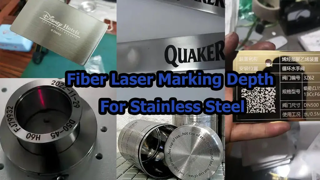
| Black marking | Stainless steel nameplates and precision components | Blackness, uniformity and surface integrity | MOPA may offer more pulse control, but testing is still required |
| Deep engraving | Tooling, dies and parts needing a measurable recess | Depth, width, edge quality and time | Usually needs more material removal and may require more power or passes |
| 2D code marking | Traceability, inventory and assembly identification | Readability with the intended reader or verifier | A code that looks clear to the eye may still fail a reader |
How to test: Send the actual logo, text or code file and state the minimum character height, code size, contrast target or engraving depth. Ask the supplier to return a sample with the tested parameters and a recorded cycle time.
Buyer Check 3: Make Sure the Lens and Detail Size Match Your Part
Small parts often have limited space for a mark. A large marking field may be useful for larger workpieces, but it is not automatically the best choice for very small text or dense codes. Lens selection changes the usable marking field and the optical conditions under which details are produced.
JQ Laser’s published fiber configurations use a typical 110 × 110 mm standard field, with other lens fields available depending on configuration. The published technical reference also lists approximate minimum line widths of 0.01–0.02 mm and minimum character sizes of about 0.1–0.2 mm under suitable conditions. These are reference values, not guaranteed results on every metal or lens.
What to Send the Supplier
- The overall part dimensions and the exact area available for marking.
- The smallest character height and thinnest line in the artwork.
- The code type and actual code dimensions, including the cell or module size where relevant.
- The lens or marking field currently being considered.
- Whether the surface is flat, curved, recessed or close to a raised edge.
How to Verify It
Run a sample using the actual artwork and intended lens. Inspect the smallest characters, line gaps, code modules and edges under consistent lighting. If a 2D code is required, test it with the intended reader or verifier. Repeat the test at the edges of the required marking area if the part will be positioned there.
Limitation: A published minimum character size does not guarantee that every character will remain readable on every material. Lens quality, focus, surface condition, artwork and inspection conditions all matter.
Buyer Check 4: Choose 20W, 30W or 50W Based on the Job
For small metal components, it is usually more useful to start from the required mark and cycle time than from the highest power you can afford. JQ Laser publishes 20W, 30W, 50W and 100W fiber configurations. The following comparison uses its published product information and public market reference ranges; prices are not fixed JQ Laser quotations.
| Power | Typical Starting Application | Published Price Reference | What to Verify |
|---|---|---|---|
| 20W | Logos, serial numbers, small labels and many standard metal marks | USD 900–1,600 reference | Required detail, contrast and cycle time |
| 30W | General production marking and repeated batches | USD 1,100–2,000 reference | Actual cycle time and whether extra power improves the bottleneck |
| 50W | Higher throughput or more demanding engraving tasks | USD 1,500–3,500 reference | Depth per cycle, passes, heat effects and total production cost |
| 100W | Higher material removal or demanding industrial production | USD 2,800–7,000 reference | Whether the application truly needs this capacity |
These price ranges are public market references from JQ Laser product content, not guaranteed prices or a like-for-like quotation. Source brand, lens, galvo scanner, enclosure, rotary axis, automation, shipping and service terms can change the final cost.
A Practical Power Decision
- Choose 20W as the first test candidate when the job is mainly logos, serial numbers or simple codes and the cycle-time target is achievable.
- Compare 30W when production is regular or when the 20W cycle time is too long. Do not assume the 30W machine will be 50% faster simply because its rated power is 50% higher.
- Test 50W when throughput or material removal is the bottleneck. Confirm the required depth and quality on the actual part, rather than buying higher power for fine detail alone.
- Consider MOPA when pulse control is important, such as selected black-marking or color-marking jobs on stainless steel. MOPA is a source type, not simply a higher-power version of a standard fiber laser.
Buyer Check 5: Check the Fixture Before You Blame the Laser
Small metal parts are easy to mishandle. A part can sit slightly tilted, rotate inside a loose nest, or move because the fixture contacts only a small area. The resulting mark may shift even though the laser parameters have not changed.
Match the Fixture to the Workpiece
- Flat plates and small brackets: use a stable nest with defined locating surfaces.
- Repeated identical components: consider a multi-part fixture if loading and inspection remain manageable.
- Round pins, shafts and rings: evaluate a rotary chuck or suitable rotary fixture.
- Parts with several variants: use clearly defined locating features and a controlled changeover process.
- Parts with inconsistent placement: evaluate whether a camera or vision-positioning system is justified.
How to Verify Repeatability
- Load a part using the normal operator procedure.
- Mark the actual artwork and record the mark’s position relative to a defined datum.
- Unload and reload the part several times, including normal operator variation.
- Measure the mark position and inspect the smallest details on each sample.
- Repeat with different parts from the production batch if their dimensions vary.
Limitation: A vision system does not automatically fix a poor fixture or an unstable part. If the part moves during marking or the camera cannot reliably distinguish the intended reference feature, the whole locating method must be reviewed.
For suitable projects, see Rotary Axis Marking and Automation Marking Solutions.
Buyer Check 6: Verify Code Readability and the Full Cycle Time
For small components, a mark can look good to the eye and still fail a production reader. This is especially important for QR codes, Data Matrix symbols and traceability marks with tight size limits.
For 2D Codes, Define the Inspection Method
- Identify the required code type and minimum physical size.
- Confirm the reader or verifier model and its normal reading distance.
- Test the actual marked part under the expected lighting and orientation.
- Record read failures as well as successful reads; do not approve the process from one successful sample.
- Where a customer specification requires a code grade, use the specified verification method rather than a simple handheld scanner alone.
Calculate the Complete Production Cycle
Total cycle time includes more than laser scanning:
Total cycle = loading + positioning + marking + inspection + unloading + transfer or data handling.
For example, if the laser marks a part quickly but the operator spends most of the time finding the correct orientation, a better fixture may provide more benefit than a higher-power laser. If code verification is the bottleneck, adding a faster laser will not automatically increase accepted parts per hour.
How to verify: Time the normal production sequence over a representative batch. Record average cycle time, failed reads, rework and changeover time. Use accepted parts per hour—not maximum scanner speed—as the practical production measure.
Buyer Check 7: Check the Supplier, Configuration and After-Sales Support
A low machine price is not useful if the supplied configuration cannot meet the marking requirement or if you cannot obtain the correct replacement parts later. Before placing an order, ask the supplier to identify the actual components and responsibilities in writing.
Supplier and Machine Checklist
- Laser source: exact brand, model, rated power, wavelength and warranty terms.
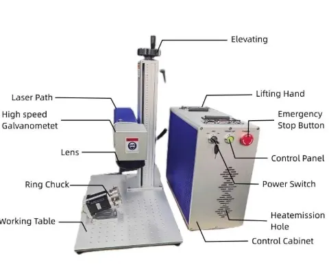
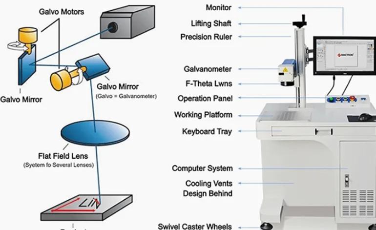
- Optics: galvanometer scanner and lens model, usable field and working distance.
- Controller and software: controller model, supported software version, file formats and variable-data requirements.
- Fixture and options: rotary axis, multi-part fixture, camera, sensors or PLC integration if required.
- Sample approval: sample photos, actual marking parameters, cycle time and acceptance criteria.
- Safety: enclosure, interlocks, extraction and other protective features appropriate to the delivered system and installation.
- Quality checks: confirm what is tested before shipment and request the relevant inspection record.
- Spare parts: availability of lenses, protective windows where applicable, fixtures and other replaceable components.
- Warranty and support: written warranty coverage, response channel, troubleshooting procedure and responsibility for repairs.
- Delivery: lead time, shipping terms, packaging, installation, training and any acceptance test.
MOQ, OEM and Lead Time
A standard machine may be available for a one-unit order, but confirm the MOQ and exact configuration with the supplier. OEM/ODM projects, custom fixtures and automated cells may require additional engineering, sample approval and a different production schedule.
JQ Laser’s published guidance uses approximately 5–7 working days as a reference production lead time for standard fiber marking machines. Treat this as a reference only: confirm the schedule in the quotation, especially when a custom fixture, special lens, enclosure or automation is involved.
Related pages: OEM & ODM, After-Sales Support, Shipping & Delivery and Service & Support.
Buyer Decision Table: Which Configuration Should You Request?
| Part and Application | Starting Configuration | Test Method | Limitation to Watch |
|---|---|---|---|
| Stainless steel screws and small fasteners | 20W or 30W fiber | Test actual part orientation, contrast and cycle time | Small curved surfaces and fixture repeatability |
| Machined aluminum components | 20W or 30W fiber | Test alloy, finish, mark contrast and required code size | Anodizing and surface variation may change the result |
| Small parts with serial numbers or 2D codes | 20W or 30W fiber; automation if needed | Use the actual reader or verifier and measure mark position | Visible marks are not proof of code compliance |
| Stainless steel parts requiring a dark black mark | Evaluate MOPA | Compare blackness, uniformity, surface integrity and time | Results vary with grade, finish and parameters |
| Tools or components requiring a deeper recess | Compare 30W and 50W; consider higher power for demanding jobs | Measure depth after a defined number of passes | More depth can mean longer cycles and more heat input |
| Parts placed inconsistently in production | Fixed fixture first; vision if justified | Repeated loading test with measured mark position | Vision cannot compensate for every mechanical error |
Sample Testing: What Should the Supplier Return?
Do not ask only, “Can your machine mark this part?” Ask the supplier to demonstrate the exact result you intend to buy.
Recommended Sample-Test Record
- Part name or sample ID, material grade and surface condition.
- Artwork file, code type, marking dimensions and target location.
- Laser source brand and model, rated power and selected lens.
- Power, speed, frequency, hatch spacing, pulse settings where applicable, and number of passes.
- Measured marking time and the method used to measure it.
- Mark position, appearance, readability and any required depth measurement.
- Photos of the sample under consistent lighting and, if relevant, inspection results.
- Repeatability results from multiple parts or repeated loading cycles.
- Customer acceptance criteria and any downstream test required.
This record gives both sides something concrete to refer to if the production result changes later. It also helps distinguish a laser-source problem from a focus, fixture, material or parameter issue.
Frequently Asked Questions
What wattage is best for small metal parts?
For many logos, serial numbers and standard identification marks, start by testing 20W or 30W fiber. Compare 50W when cycle time or engraving depth justifies the added cost. The correct choice depends on the actual part and acceptance criteria.
Does a 50W fiber laser always produce finer details than a 20W machine?
No. Fine detail depends on the optical setup, focus, artwork, material and process parameters. Higher power is mainly a capacity choice; it does not automatically make small text or codes clearer.
Can a fiber laser mark stainless steel, aluminum, brass and copper?
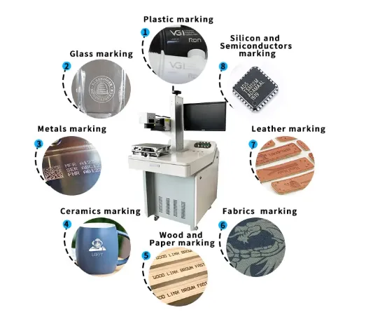
Fiber lasers are widely used for metal marking, including these materials. The required contrast, surface finish and process settings vary by alloy and application, so sample testing is recommended.
Do I need MOPA for small metal parts?
Not for every job. Standard fiber can be suitable for ordinary identification marks. Evaluate MOPA when adjustable pulse duration is valuable, such as for selected black-marking or color-marking applications on stainless steel.
How can I ensure a small QR or Data Matrix code is readable?
Define the code size and inspection method before testing. Use the actual artwork and material, then check the mark with the intended reader or verifier. For strict customer requirements, follow the specified verification standard.
Should I buy a vision system for small parts?
Only if normal fixture positioning cannot meet the required placement tolerance or if part orientation varies in production. Test the fixture first. Vision adds value when it solves a measured positioning problem and the camera can reliably identify the intended reference feature.
Can I order one machine for my factory?
A one-unit order may be possible for a standard configuration, subject to confirmation. Custom fixtures, OEM requirements and automation may change the MOQ, cost and lead time. Confirm the exact scope in writing.
What should I send for a quotation?
Send part photos or drawings, material and surface finish, artwork, marking dimensions, daily volume, target cycle time, required depth or contrast, inspection requirements and any fixture or automation needs. Actual samples are preferable for final approval.
Choose the Right Fiber Laser for Your Small Metal Parts
Send JQ Laser your real component, marking artwork and production target. We can evaluate whether a 20W, 30W or 50W fiber laser is a sensible starting point and identify the lens, fixture and inspection method that should be tested.
For repeat production, ask for a documented sample result, marking time and acceptance criteria before finalizing the machine specification.
Related Resources
Technical Notes and Source Traceability
Power options, wavelength, standard marking field, reference speed, line width and character-size figures in this guide are based on JQ Laser’s published fiber laser product pages. Actual performance depends on the selected source, lens, scanner, material, artwork and test conditions.
The price ranges are public market reference values published on JQ Laser product content, not fixed quotations. Confirm the exact laser-source model, optics, controller, fixture, warranty, delivery terms and included accessories in the final quotation.
For each approved application, retain the part ID, material and surface finish, artwork file, laser source model, lens, tested parameters, sample photos, marking time, inspection method and acceptance result. This makes the sample test traceable to the production machine and supports later troubleshooting.