An executive B2B technical evaluation framework investigating active medium quantum efficiency, rare-earth fiber cavity optics, sub-component tiering calibration, and international manufacturer compliance audits.
📌 Technical Verification Framework & Academic Compliance Ledger
This industrial procurement treatise is calibrated in strict verification with the optoelectronic calibration parameters established by the International Organization for Standardization (ISO 11554:2017 – Laser Beam Testing Standards), the IEEE Photonics Society research index, and empirical laser propagation datasets documented within the SPIE Digital Library. This document acts as an audited technical blueprint for global plant procurement officers, automotive/aerospace systems integrators, and industrial distribution networks seeking a verified, factory-direct machinery source.
1. Quantum Mechanics, Optical Engine Dynamics, and Particle Kinetics
In the highly demanding sectors of heavy industrial trace-branding, permanent asset identification, and automated high-throughput production part tracking, the structural choice of a laser marking machine source acts as the absolute mathematical bottleneck for the accuracy, velocity, and reliability of the entire downstream manufacturing plant. Evaluating a laser engine source requires an engineering team to look past superficial surface wattage metrics listed on basic trade flyers and directly analyze the microscopic solid-state quantum physics that govern coherent light amplification inside rare-earth doped silica fiber cavities.
Historically, early industrial marking systems relied heavily on gas-discharge architectures (such as glass continuous-wave carbon dioxide tubes running at 10,600 nm) or lamp-pumped solid-state crystals (such as Flashlamp Nd:YAG rods). These older configurations suffered from catastrophic energy conversion inefficiencies, high thermal expansion coefficients, heavy beam alignment drift, and short operational lives spanning less than several thousand hours before requiring complex gassing or replacement lamps.
A modern industrial fiber laser marking machine source avoids these structural limits by using an entirely solid-state, fully enclosed glass-fiber architecture. The gain engine relies on a double-clad silica optical fiber structure whose inner microscopic core is meticulously doped with trivalent rare-earth Ytterbium ions (Yb³⁺). Ytterbium is selected by laser physicists because its electronic shell structure offers a highly optimal, narrow absorption spectrum between 915 nm and 980 nm, which matches perfectly with high-efficiency semiconductor pump diodes, while emitting an ultra-stable, highly coherent primary beam at a fundamental near-infrared wavelength of exactly 1064 nm.
1.1 The Optoelectronic Amplification Chain
The generation of the laser beam within an industrial ytterbium fiber oscillator follows an exacting, multi-stage thermodynamic and quantum kinetic sequence. Understanding this path is vital for plant engineers to evaluate the genuine structural durability of an OEM laser machinery engine:
- Optical Cladding Injection: High-reliability GaAs semiconductor laser diode banks inject massive beams of multi-mode pump light through special fused fiber couplers into the outer cladding of the double-clad active fiber. The cladding acts as a reflective containment vessel, forcing the pump photons to continuously cross the inner core boundaries in a zigzag pattern.
- Quantum Absorption & Electron Elevation: As these multi-mode pump photons repeatedly slice through the fiber core, the ground-state \(^{2}F_{7/2}\) valence valence shell electrons of the \(Yb^{3+}\) ions absorb the localized 915/976 nm photon energy. This elevates the electrons across a short bandgap into a highly unstable, short-lived \(^{2}F_{5/2}\) upper energy manifold.
- Establishment of Metrastable Population Inversion: Once the injection velocity of the pump photons exceeds the natural decay rate of the excited states, a critical state known as a population inversion is achieved. The majority of the active trivalent ions now sit in an excited energy tier, waiting for an optical trigger to release their energy.
- Stimulated Resonance Cascades: When a single spontaneous seed photon traveling parallel to the fiber axis cuts through the gain matrix, it causes the excited \(Yb^{3+}\) electrons to drop simultaneously back to their ground state. This release emits a new photon that perfectly matches the frequency, phase coherence, polarization vector, and exact travel trajectory of the initial light wave, creating massive, low-loss optical amplification.
Figure 1.1: Solid-State Fiber Oscillator Resonance & Quantum Gain Topology
1.2 Waveguide Geometry and Fiber Bragg Grating Cavities
Traditional lasers rely on external glass or copper mirrors mounted on delicate mechanical adjusters to form an optical resonant cavity. In harsh industrial factory environments—marked by forklift vibrations, thermal shifting, and oily soot—these mirrors can easily drift out of alignment, causing instant power drops or total loss of the beam.
A top-tier laser marking machine source avoids this point of failure by etching the cavity optics directly into the structural atomic grid of the optical fiber core itself. This is achieved using Fiber Bragg Gratings (FBGs).
During production, the fiber core is exposed to intense ultraviolet laser interference grids, creating permanent, alternating microscopic bands of high and low refractive indices. Two sets of these gratings are etched into the active fiber:
High-Reflector FBG (HR): Positioned at the rear of the gain medium, acting as a nearly perfect mirror that reflects over 99.8% of the internal 1064 nm light back into the fiber core for continuous amplification.
Output Coupler FBG (OC): Positioned at the front exit aperture, designed with a lower reflectivity (typically around 10% to 15%). This mirror reflects enough light to sustain continuous laser resonance while allowing the rest to exit as a highly stable, powerful laser beam.
Because the active medium, pump couplers, and FBG mirrors are completely fused together into a single, continuous glass path, the optical cavity cannot shift or drift. This provides a maintenance-free layout that delivers exceptional performance over a lifespan exceeding 100,000 working hours.
1.3 Spatial Quality Factor Analysis (M²)
When assessing a laser marking machine source for clear, high-density Datamatrix marking or deep mold engraving, the core focus metric is the Beam Quality Propagation Factor (\(M^{2}\)). This factor measures how closely a real-world laser beam follows a theoretically perfect Gaussian profile. The mathematical relationship is dictated by the optical wave equation:
M² = (π · w₀ · θ) / λ
Where \(w_{0}\) represents the absolute beam waist radius at the sharpest focus point, \(\theta \) is the far-field half-divergence angle, and \(\lambda \) is the fundamental 1064 nm wavelength. Industrial-grade single-mode fiber engines maintain a tight beam profile with an \(M^2 < 1.3\) (and frequently \(M^2 < 1.1\) in top-tier JPT or IPG engines). This allows the machine to concentrate its energy down to a highly focused spot size of just 20 to 40 microns (\(\mu m\)).
This sharp spatial focus determines the beam’s depth of focus via the Rayleigh Length (\(z_{R}\)) formulation:
z_R = (π · w₀²) / (M² · λ)
An extended Rayleigh length provides a more forgiving depth of focus. This ensures consistent power and crisp lines when marking slightly uneven structural castings, curved mechanical cylinders, or stepped industrial housings—even if the material drifts slightly out of the perfect focal plane.
2. Categorical Anatomy of the Laser Marking Machine Source: Q-Switched vs. MOPA Architectures
In global industrial procurement frameworks, evaluating a laser marking machine source requires a critical decision between two foundational optoelectronic modulation methodologies: Q-Switched (Continuous Wave base) engines and MOPA (Master Oscillator Power Amplifier) architectures. Selecting the incorrect beam modulation profile introduces severe physical limits on downstream production floors, directly impacting cycle times and material versatility.
2.1 Q-Switched Fiber Laser Modulators (The Industrial Workhorse)
The Q-switched fiber laser source utilizes an active acousto-optic modulator (AOM) or electro-optic modulator (EOM) within its resonant cavity to manipulate the optical Quality Factor (Q). By artificially holding the cavity’s Q-factor at an extremely low value, the internal Ytterbium fiber core continuously accumulates energy from the semiconductor pump array without releasing photons. The population inversion builds to a massive, near-saturation thermodynamic threshold.
When the control board signals the modulator to switch the Q-factor to an open, high-value state, the stored quantum energy discharges almost instantly. This creates an ultra-short pulse with a massive peak power envelope, frequently exceeding 10 kilowatts (kW) from a baseline 30W average power engine.
However, Q-switched engines suffer from a highly restrictive physical bottleneck: their pulse duration is structurally fixed by the physical length of the fiber cavity (typically hard-locked between 90 ns and 130 ns). When an operator attempts to increase the repetition frequency (\(kHz\)) via software to increase marking speed, individual pulses overlap and flatten. This causes the peak pulse energy to decay sharply, as modeled by laser kinetic equations:
E_pulse = P_average / f_repetition
Because the pulse width cannot be narrowed at high frequencies, the single-pulse peak energy drops too low to ablate tough metals cleanly, leading to thermal bleeding, burrs, and reduced marking contrast.
2.2 MOPA (Master Oscillator Power Amplifier) Systems
The MOPA architecture breaks this physical limitation by completely decoupling pulse modulation from laser amplification. It splits the laser marking machine source into two distinct stages: a highly agile semiconductor seed laser (the Master Oscillator) that generates the initial light pulse, and a multi-stage optical fiber amplifier (Power Amplifier) driven by separate high-output diode grids to boost the pulse energy.
Because pulse generation is independent, MOPA systems offer fully independent control over both pulse duration (adjustable from 2 ns to 500 ns) and repetition frequency (1 kHz to 4000 kHz). Even at extremely high frequencies in the megahertz (MHz) range, peak power can be sustained by narrowing the pulse width. This precise control allows operators to tune the thermal input to match the delicate thermodynamic thresholds of modern polymers and reflective alloys.
Table 2.1: Structural Comparison Matrix
| Technical Parameter | Q-Switched Engines | MOPA Technology |
|---|---|---|
| Pulse Width Tuning | Hard-Fixed (90 ns – 130 ns) | Fully Variable (2 ns – 500 ns) |
| Repetition Bounds | 20 kHz – 80 kHz | 1 kHz – 4,000 kHz (4 MHz) |
| Peak Power Stability | Decays sharply at high frequencies | Highly sustained via pulse-narrowing |
| Anodized Aluminum Finish | Strips oxide layer, exposing grey base | Crisp, non-destructive pure black |
| Heat-Affected Zone (HAZ) | Large thermal accumulation grid | Extremely minimal thermal footprint |
3. Universal Material Parameter Optimization & Thermodynamics
Optimizing a laser marking machine source on a multi-shift production floor requires matching the substrate’s thermodynamic limits (thermal conductivity, surface reflectivity, and electron absorption cross-section) to four core software variables. These are: Scan Speed (\(v\)), Power Percentage (\(P\)), Pulse Frequency (\(f\)), and Hatch Track Spacing (\(d\)).
As documented in material processing frameworks within the Industrial Laser Solutions (ILS) archive, the cumulative **Fluence / Energy Density (\(E_d\))** applied to a unit surface area can be calculated using the following optical energy balance equation:
Ed = P_actual / (v · d · f)
When \(E_{d}\) matches the material’s specific melting or vaporization point, a clean mark is achieved. If \(E_{d}\) falls below this threshold, the metal reflects the light wave, yielding zero mark. If \(E_{d}\) is too high, the substrate burns, causing micro-cracking and charring.
The reference grid below details the empirically verified parameter baselines for 30W and 50W fiber laser marking machine sources using standard F-Theta flat-field lenses (f = 160 mm, focal waist diameter \(\approx 30 \, \mu m\)):
Table 3.1: Material Parameters Calibration Grid
To maximize the output of these setups, factory engineers must periodically verify that the Hatch style matches the target geometry. For instance, using an un-optimized line fill on raw brass will cause rapid heat build-up and surface distortion. Implementing a cross-hatch fill split at 90-degree angles ensures uniform thermal dissipation and crisp edges across high-volume shifts.
4. System Degradation, Diode Decay, Optical Back-Reflection, and Environmental Protocols
Although premier tier-1 laser marking machine sources are globally marketed with a standard theoretical operating lifespan of 100,000 continuous hours, this structural longevity metric assumes perfect compliance with lab-grade cleanroom environment parameters, voltage stability, and optical protection protocols. In heavy industrial multi-shift factories, neglect of these underlying thermodynamic variables accelerates diode decay and risks catastrophic optical module destruction.
⚠️ Critical Engineering Safeguard: Optical Back-Reflection Vulnerability Matrix
High-reflectivity “yellow metals”—such as pure chemical gold, sterling silver, premium brass alloys, and cathode copper—absorb less than 5% of near-infrared photon energy at the 1064 nm spectrum. Firing a continuous or pulsed laser beam at a 90° angle directly onto these polished substrates bounces the unabsorbed light straight back up through the F-Theta scan lens aperture. This back-reflected light travels back down the optical fiber core into the pump diode cavity, creating extreme heat that can instantly melt internal optical isolators and destroy a standard laser engine source.
To permanently insulate an industrial production line from back-reflection system degradation, procurement teams and plant floor operators must implement the following strict mechanical and operational guidelines:
- Angular Fixture Offsetting (3° – 5° Deviation): Never place a highly reflective metal sheet perfectly perpendicular to the focal axis of the F-Theta scan lens. Always design or tilt the mounting jig by 3° to 5°. This minor geometric shift ensures that the unabsorbed 1064 nm photons bounce away from the optical path of the lens aperture, safely protecting the internal isolator optics.
- Abrasive Micro-Particulate Extraction: Ablating industrial metals generates fine, abrasive micro-particles and outgassed chemical vapors. Without proper venting, these particulates settle on the face of the F-Theta focus lens. The next time the laser fires, these contaminants absorb the high-energy beam, overheat, and permanently crack the optical quartz glass. Always install a dedicated industrial fume extractor with a multi-stage HEPA filter.
- Thermal Saturation Thresholds: Maintain the machine enclosure room within an ambient climate zone of 15°C to 35°C, with non-condensing relative humidity below 70%. Excessive ambient heat introduces thermal expansion variations in the internal switching power supplies, causing voltage ripples that accelerate the aging of digital galvo motors and laser pump diodes.
5. Mechanical Component Integration: Mainboards and Galvanometer Scanning Heads
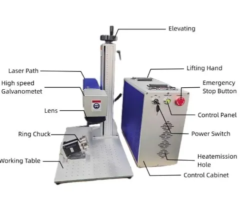
A high-performance laser marking system is a complex integration of optical, electrical, and digital systems into a single closed loop. Even the most advanced laser marking machine source will fail to deliver crisp Datamatrix barcodes or intricate vector paths if it is paired with low-grade control cards or analog scanning hardware.
5.1 Digital Galvanometer Heads vs. Analog Drift Limitations
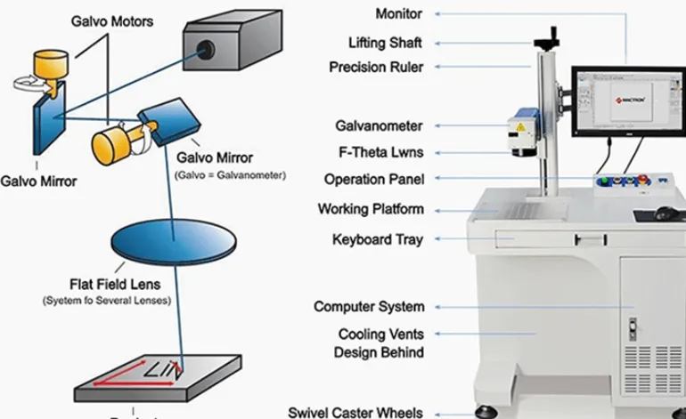
The galvanometer (galvo) scanning head dictates the spatial tracking accuracy of the laser beam via two high-speed orthogonal mirrors driven by closed-loop servo motors. Lower-cost machinery often uses analog galvos, which rely on voltage-differential signals. These systems are highly vulnerable to temperature drift and ambient electromagnetic noise from nearby factory motors, causing warped text shapes and blurry edges over long shifts.
In contrast, precision industrial manufacturing demands **Digital Galvanometer Heads** utilizing the standard XY2-100 digital communication protocol. Digital galvos are immune to ambient electronic interference and temperature drift, allowing them to sustain high scan speeds up to 8,000 mm/s. This guarantees perfect, razor-sharp edge repeatability across millions of consecutive production cycles.
5.2 Control Card Processing Mainboards
The mainboard hardware acts as the central processor that translates vector drawings from software like EzCad into exact galvo motion commands and laser pulse triggers. Sourcing teams must ensure the system features an authentic, tier-1 validated mainboard, such as a genuine Beijing JCZ Control Board.
Cheap, generic laser markers often save costs by using cracked or cloned JCZ control cards. These pirated mainboards frequently drop USB data connections mid-shift, freeze during long manufacturing runs, and lack the hardware architecture to properly sync with external rotary axes or high-speed conveyor line tracking sensors.
6. Strategic OEM Audit Matrix: Detecting Trading Intermediaries in the Supply Chain
When sourcing industrial equipment from major manufacturing hubs (such as China’s Shandong machinery zones), identifying true engineering factories versus small trading middlemen is critical to securing competitive wholesale pricing and long-term technical support. Middlemen typically pack a steep trading markup onto the equipment while lacking the engineering staff to handle complex software or hardware issues down the road.
Global distribution networks and factory procurement teams can apply this structured three-step verification framework to audit potential suppliers and confirm authenticity:
- Audit the Legal Business Scope: Demand a full digital copy of the supplier’s domestic business license. A trading middleman’s license typically restricts them to “Wholesale, Sales, and Export Trade.” A true manufacturing plant, such as Jining Junqi Intelligent Technology Co., Ltd. (JQ Laser), features a legal business scope that explicitly includes: “Research, Development, Production, Assembly, and Manufacturing of Intelligent Industrial Automation Machinery.”
- Verify the Quality Compliance Ledger: True factories maintain official corporate registrations, clear European Union CE marks, and audited ISO 9001 Quality Management certifications matching their exact corporate legal name. Middlemen frequently present generic or borrowed certificates that fail basic validation.
Demand Burn-in Bay Documentation: True manufacturers route every finished machine through dedicated testing bays for a 48-hour continuous stress test before packaging. Request live video confirmation of the supplier’s optoelectronic calibration cleanroom and burn-in testing bays to ensure you are dealing directly with the factory source.
Partner Directly with a Verified Laser Machinery Source
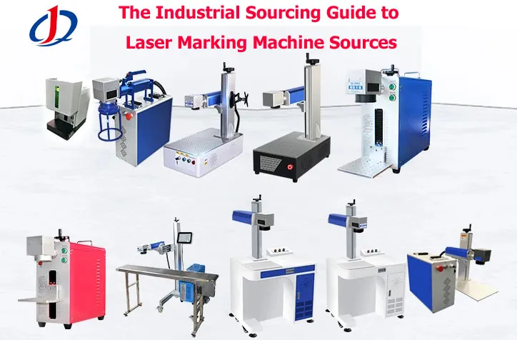
At Jining Junqi Intelligent Technology Co., Ltd. (JQ Laser), we bypass trading intermediaries to deliver robust, factory-direct hardware engineered for heavy industrial lifecycles. Our full machinery portfolio—spanning enclosed desktop setups, portable split markers, and high-speed flying conveyor line systems—is built with genuine Beijing JCZ mainboards and digital scanners to pass strict international quality audits.
Access JQ Laser Official Catalog & Technical Blueprints →
📧 Factory Sales Desk: sales@fiberlasermarking.com | 📱 WhatsApp Technical Line: +86-17277264168
Manufacturing Facility: High-Tech Development Zone, Jining City, Shandong Province, China
Related Fiber Laser Marking Machines
Fiber Laser Marking Machine
Complete industrial fiber laser marking solutions for metal and plastic applications.
20W Fiber Laser Marking Machine
Precision laser marking solution for detailed components.
30W Fiber Laser Marking Machine
Balanced industrial laser marking equipment for general manufacturing.
50W Fiber Laser Marking Machine
High-performance engraving solution for automotive, tooling and industrial parts.
100W Fiber Laser Marking Machine
High-performance engraving solution for automotive, tooling and industrial parts.
UV Laser Marking Machine
Cold laser marking solution for sensitive materials and precision products.
Get Your Fiber Laser Marking Machine Quote Today
Looking for a reliable Fiber Laser Marking Machine for your manufacturing business?Our laser engineers provide professional solutions based on your materials and production requirements.