EV COMPONENT IDENTIFICATION & TRACEABILITY
EV Automotive Parts Marking: Laser Marking for Electric Vehicle Components
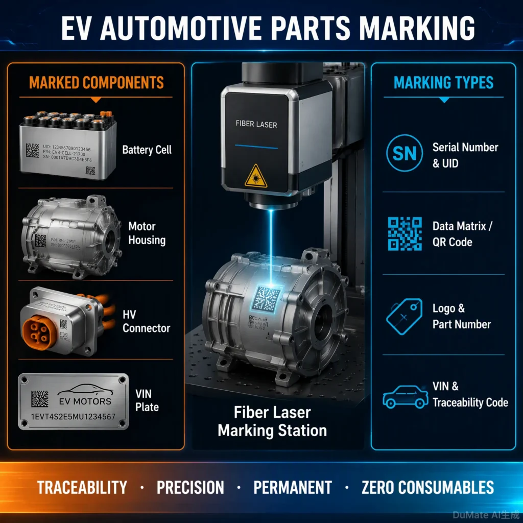
EV automotive parts marking uses laser technology to apply serial numbers, Data Matrix codes, QR codes, logos and production information to electric vehicle components. JQ Laser helps manufacturers evaluate fiber, MOPA fiber and UV laser marking according to the material, surface condition, code size, readability target and production workflow.
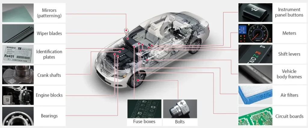
Applications may include electric motor housings, inverter enclosures, aluminum cooling components, battery trays, connectors, electronic housings and selected plastic parts. The correct solution depends on the actual component—not simply whether it belongs to an electric vehicle.
What Is EV Automotive Parts Marking?
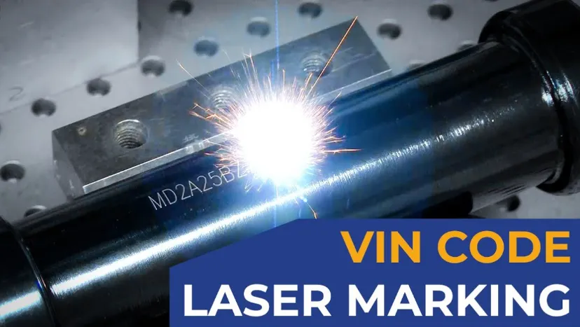
EV automotive parts marking is the process of identifying electric vehicle components with permanent or application-specific marks. These marks can support manufacturing identification, assembly verification, quality control, inventory management and after-sales traceability.
Unlike a label that can peel, fade or be replaced, a laser mark is formed by changing the surface or a suitable coating of the workpiece. Depending on the material and process, the result may be a surface-color change, a dark or light contrast mark, or a controlled engraved mark. Durability must be verified against the component’s actual service environment and downstream processes.
For automotive suppliers, the challenge is not just creating a visible mark. The code must be positioned correctly, remain readable under the specified inspection conditions, and fit into the production process without damaging the component or disrupting takt time.
Which EV Components Can Be Laser Marked?
The following are common application areas to evaluate. The final laser source and parameters should be selected after testing the actual material grade, finish, coating and marking location.
1. Electric Motor Housings
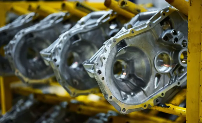
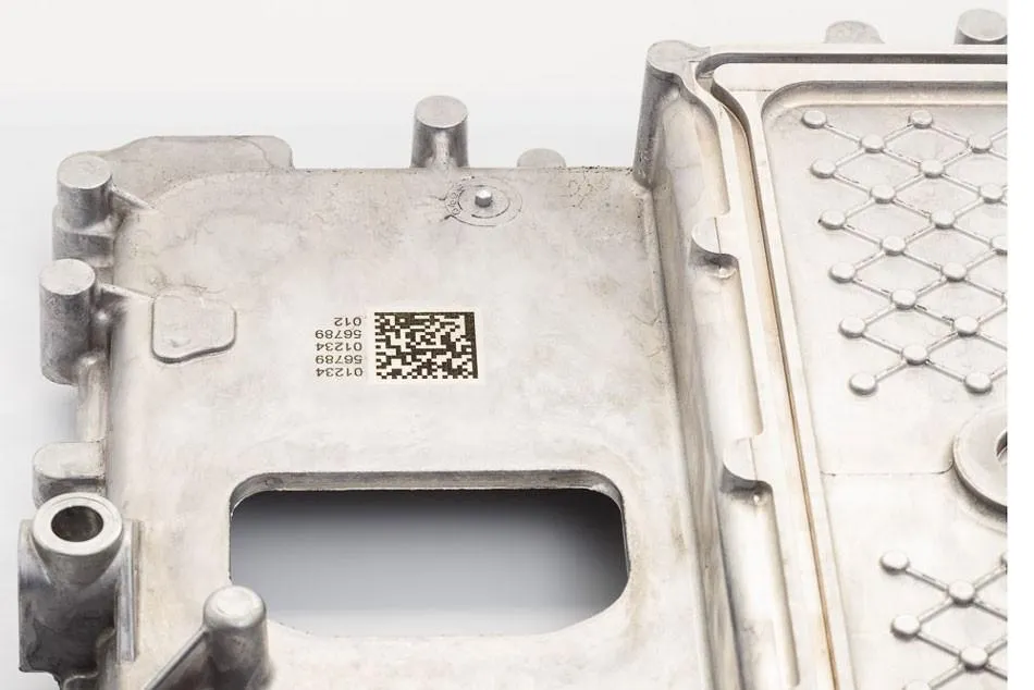
Mark aluminum or steel housings with part numbers, serial numbers, supplier IDs, logos and 2D traceability codes. Cast surfaces, curved areas and dimensional variation may require a dedicated fixture or positioning compensation.
2. Inverter & Power Electronics Housings
Identify inverter cases, converter enclosures, cooling plates and selected electronic assemblies. The marking process must account for coatings, machined surfaces, electrical clearances and any restrictions on heat or particulate generation.
3. Battery Trays & Covers
Apply identification codes and manufacturing information to suitable battery tray, cover and enclosure surfaces. Large parts may need a larger marking field, a multi-position fixture, a robot or a gantry-based system.
4. Connectors & Electrical Components
Mark connector bodies, terminals, brackets and electrical component housings where the material and geometry permit. For small parts, narrow marking areas or heat-sensitive polymers, UV laser testing may be worth considering.
5. Drive Units, Gearboxes & Metal Parts
Mark gear housings, shafts, brackets, fasteners and drive-unit components with serials, batch codes or Data Matrix symbols. A rotary axis or custom fixture can help position cylindrical or irregular parts.
6. Selected Plastic & Interior Parts
Identify compatible engineering plastics, switch housings, covers and interior components. Results vary substantially with polymer composition, pigment, additives and surface finish; test for contrast, deformation and readability before production.
For broader automotive applications, see our Automotive Parts Marking Solution.
Common Marking Requirements for EV Manufacturers
| Marking Requirement | Typical Content | What to Validate |
|---|---|---|
| Part identification | Part number, model, logo | Contrast, dimensions, location and repeatability |
| Unit-level traceability | Serial number, Data Matrix, QR code | Code readability, data accuracy and inspection method |
| Batch management | Lot number, date or shift code | Variable-data input, changeover control and error prevention |
| Assembly verification | Variant ID, assembly reference | Correct code-to-part association and database workflow |
| Long-term identification | Permanent component information | Readability after relevant wear, cleaning, coating or corrosion tests |
Important: A laser-marked code is not automatically compliant with every automotive customer specification. Code size, contrast, symbol quality, location and verification criteria must be agreed with the customer and validated under the required inspection standard.
How to Choose the Right Laser for EV Parts Marking
Fiber, MOPA fiber and UV lasers are useful starting points for many EV component applications, but none is the best choice for every part. Selection should begin with the substrate and required result, followed by the production requirements.
| Laser Type | Potential Applications | Key Considerations |
|---|---|---|
| Fiber Laser | Metal housings, brackets, shafts, fasteners, serial numbers and 2D codes | Suitable for many metals; contrast and depth depend on alloy, surface treatment and parameters. |
| MOPA Fiber Laser | Selected anodized aluminum, stainless steel and applications requiring greater pulse control | Can offer more control over pulse parameters; the actual result still requires material testing. |
| UV Laser | Selected plastics, electronic parts and heat-sensitive substrates | May reduce unwanted thermal effects on suitable materials; it does not guarantee damage-free marking. |
| CO2 Laser | Selected non-metallic or coated materials, depending on the component | Confirm absorption and mark quality for the specific polymer, coating or non-metal substrate. |
Fiber vs. MOPA vs. UV: A Practical Selection Example
- Machined aluminum motor housing: Start by testing a fiber laser. If the surface treatment or contrast requirement is difficult, compare a MOPA configuration.
- Anodized aluminum cover: Test standard fiber and MOPA settings against the required contrast, coating integrity and code readability.
- Plastic connector housing: Evaluate UV and other compatible options on the exact polymer grade. Check for melting, discoloration, burrs and deformation.
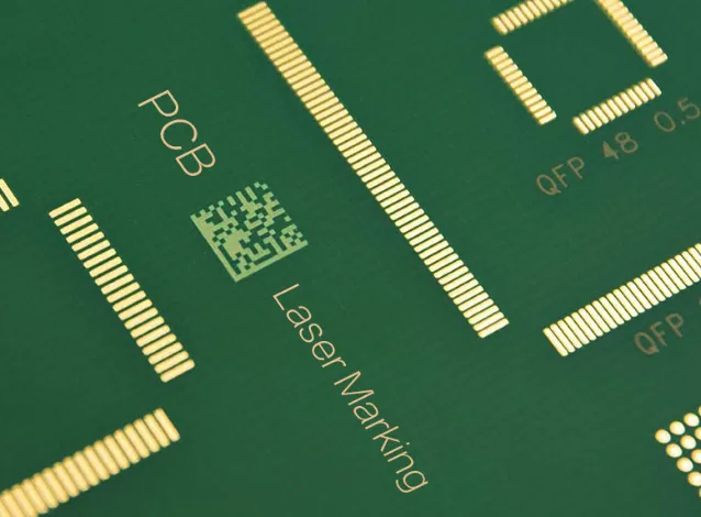
- PCB or sensitive electronic assembly: Confirm whether marking is allowed on the specified area, and validate thermal effects, particles and electrical functionality.
- Deep identification on a metal part: Compare power, pulse settings, number of passes and acceptable cycle time. Do not select a high-power laser based on wattage alone.
EV Component Material and Process Guide
| Material or Surface | Starting Point | Test Priorities |
|---|---|---|
| Aluminum alloy or cast aluminum | Fiber; MOPA if needed | Cast texture, contrast, focus variation and code readability |
| Stainless steel | Fiber or MOPA | Darkness, surface oxidation, depth and downstream corrosion requirements |
| Carbon steel | Fiber | Surface scale, oil, coating, mark contrast and corrosion protection |
| Anodized aluminum | Fiber or MOPA | Coating color, substrate exposure, contrast and appearance consistency |
| Engineering plastics | UV or a tested compatible laser | Polymer grade, pigment, additives, thermal damage and readability |
| Copper or copper alloy | Application-specific fiber/MOPA testing | Reflectivity, surface condition, contrast and component function |
| PCB or electronic substrate | UV evaluation where appropriate | Substrate damage, particles, component clearance and electrical performance |
These are starting points, not guaranteed recipes. For coated parts, plastics, copper, PCBs and safety-critical components, testing should include any relevant post-marking cleaning, coating, environmental and functional checks.
Data Matrix, QR Codes and EV Traceability
EV manufacturers may need to connect each component with a production record. A laser marking system can mark fixed information such as a part number or logo, as well as variable data such as a serial number, batch code or 2D symbol.
A Typical Traceability Workflow
- Receive product data: Obtain the serial number or code content from the operator, production software, PLC or an approved data interface.
- Verify the part: Use a fixture, sensor or optional vision system to confirm that the correct component is in the marking position.
- Apply the mark: Run the approved marking file and parameter set for that component and material.
- Inspect the result: Use a barcode reader or code verifier according to the customer’s acceptance criteria.
- Record the result: Where the system supports the required interface, connect the result to the production record and flag failures for operator review.
Laser marking alone does not create a complete traceability system. Data validation, code uniqueness, database integration, verification equipment and reject handling should be defined as part of the project.
Manual, Semi-Automatic or Inline EV Marking?
| Configuration | Suitable For | Main Design Consideration |
|---|---|---|
| Manual workstation | Prototypes, small batches, multiple part types | Operator loading, fixture repeatability and safety enclosure |
| Semi-automatic station | Repeat production with controlled part placement | Clamping, sensors, recipe selection and operator workflow |
| Conveyor or indexed line | Repetitive production with defined takt-time targets | Part spacing, trigger timing, tracking and downstream inspection |
| Robot or custom automation | Large, heavy, irregular or multi-face components | Reach, cycle-time balance, guarding, communication and maintainability |
Explore our Automatic Laser Marking Machine, Conveyor Laser Marking System and Automation Marking Solution pages for configuration ideas.
How to Evaluate Marking Speed and Production Throughput
The maximum scanner speed shown in a machine specification is not the same as the number of finished parts a production line can process per hour. EV parts may require complex 2D codes, multiple lines of text, deep marks, positioning adjustments or post-marking verification.
A more useful estimate considers the complete cycle:
Total cycle time = loading + positioning + marking + inspection + unloading + any required transfer or data-handling time.
For example, a faster laser may provide limited benefit if the main bottleneck is manual loading or code verification. Conversely, a stable fixture and automatic part positioning may improve the process even when the laser source remains unchanged.
Before specifying a cycle-time target, provide the required code content, marking dimensions, number of marks per part, target parts per minute, loading method and inspection requirements. A trial using representative production parts is the most reliable way to confirm feasibility.
Sample Testing Before Machine Selection
JQ Laser recommends evaluating the actual component before finalizing the laser source, power, lens, fixture or automation design. A photo is useful for an initial discussion, but it cannot fully establish material composition, surface treatment or the achievable mark quality.
What Should Be Tested?
- Actual material grade, coating, anodizing, paint or surface finish.
- Marking content, code size, logo detail and available marking area.
- Required contrast, engraving depth or surface appearance.
- Code readability using the customer’s reader or verification criteria.
- Position tolerance, focus variation and workpiece-to-workpiece differences.
- Potential damage, discoloration, burrs, particles or effects on component function.
- Repeatability across multiple samples and the estimated production cycle.
- Any downstream cleaning, coating, corrosion, wear or environmental testing required by the customer.
Testing should document the material and surface condition, laser configuration, lens, parameter set, sample result and acceptance criteria. This makes the final equipment specification more reliable and helps reduce commissioning risk.
JQ Laser EV Marking System Configuration
Jining Junqi Intelligent Technology Co., Ltd. (JQ Laser) supplies laser marking equipment and can evaluate configurations for automotive component identification and industrial production. The appropriate system depends on the workpiece, mark requirements and level of automation.
- Laser source: Fiber, MOPA fiber or UV, selected after material and mark testing.
- Marking head and lens: Selected according to the required marking area, working distance and feature size.
- Fixture: Designed around part geometry, datum surfaces, repeatability and operator access.
- Automation: Optional sensors, PLC interfaces, conveyor, rotary axis, robot integration or vision positioning, depending on the project.
- Marking software: Configuration depends on the controller and required variable-data workflow.
- Safety: Enclosure, interlocks, extraction and other protective measures must be specified for the actual laser system and installation.
For a project quotation, confirm the laser source and brand, rated power, marking lens, fixture, controller, automation scope, inspection method, acceptance criteria, delivery terms and installation responsibilities in writing.
Information to Include in Your EV Marking RFQ
To help us assess your application, please prepare as many of the following details as possible:
- Part name, dimensions, weight and clear photos of the marking area.
- Material grade and surface treatment, including coatings or anodizing.
- Mark content: serial number, Data Matrix, QR code, logo or other information.
- Required mark size, contrast, depth and position tolerance.
- Target cycle time, daily output and number of product variants.
- Manual, semi-automatic, conveyor, robot or existing production-line integration.
- Code reader or verifier requirements and any customer-specific standards.
- Required electrical supply, factory layout and preferred delivery destination.
With these details, JQ Laser can evaluate a suitable laser configuration and identify which points need sample testing before a final proposal.
Frequently Asked Questions About EV Automotive Parts Marking
Which laser is best for EV automotive parts marking?
Fiber lasers are a common starting point for metal housings, brackets and many machined components. MOPA fiber can provide additional pulse control for selected surface finishes and contrast requirements. UV lasers may be appropriate for selected plastics and sensitive electronic substrates. The best choice depends on the actual material, required mark and validation criteria.
Can a laser mark Data Matrix codes on EV components?
Yes, laser systems can mark Data Matrix symbols on suitable EV components. Code size, contrast, module size, surface condition, marking location and scanner performance all affect readability. Validate the code with the intended reader or verifier and the customer’s acceptance criteria.
Can laser marking be used on aluminum motor housings and inverter cases?
Yes, many aluminum housings can be laser marked. Cast texture, alloy composition, machining, anodizing and dimensional variation can change the result. Testing should confirm contrast, code readability, focus tolerance and any downstream surface requirements.
Is UV laser marking suitable for EV plastic connectors?
UV laser marking is worth evaluating for selected plastic connectors and electronic components, particularly where controlled heat input is important. Results depend on polymer type, pigment, additives and geometry. Test for melting, discoloration, deformation and functional impact before approving the process.
Can the marking machine be integrated into an EV production line?
Yes, a suitable system can be designed with fixtures, sensors, PLC interfaces, conveyors, rotary positioning, robots or optional vision systems. The integration scope should define data exchange, triggering, part tracking, fault handling, safety and code verification.
How do we confirm the marked code will remain readable?
Define the required reader or verification method, mark location, code dimensions and acceptance criteria first. Then test representative parts and perform any required downstream cleaning, coating, wear, corrosion or environmental checks. Long-term readability should be demonstrated against the customer’s actual requirements rather than assumed from the marking method alone.
Does JQ Laser offer customized fixtures and automation?
JQ Laser can evaluate custom fixtures and automation options such as conveyor handling, rotary positioning, PLC interfaces and optional vision positioning. The final scope depends on the workpiece, production target, line layout and interface requirements.
What information is needed to receive a quotation?
Send part photos or drawings, material and surface treatment, marking content, required code size, target cycle time, production volume, automation requirements and delivery destination. If possible, provide actual samples so the marking result can be evaluated before the configuration is finalized.
Plan Your EV Automotive Parts Marking Project
Whether you need to mark an aluminum motor housing, an inverter case, a battery enclosure, a connector or another EV component, begin with the actual part and the required identification result.
Send JQ Laser your material details, marking artwork, code requirements and production target. We can help evaluate the laser type, lens, fixture and automation options that should be tested for your application.