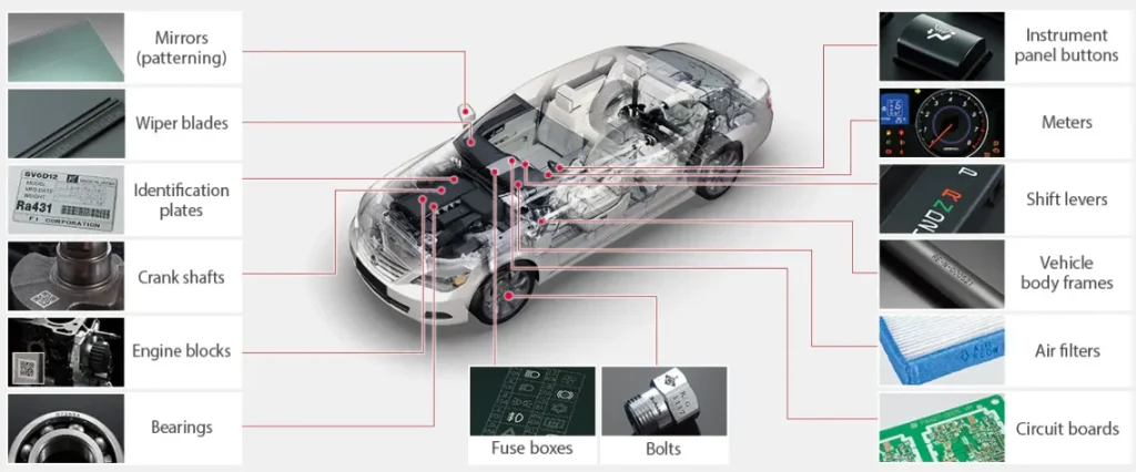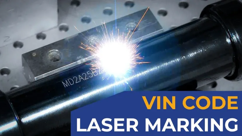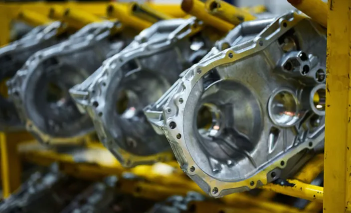
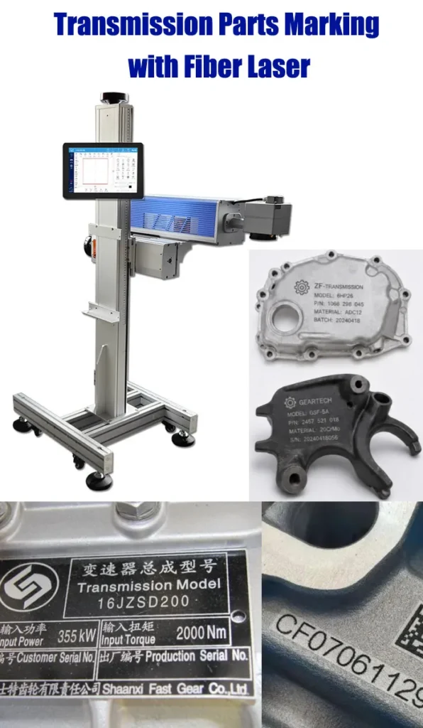
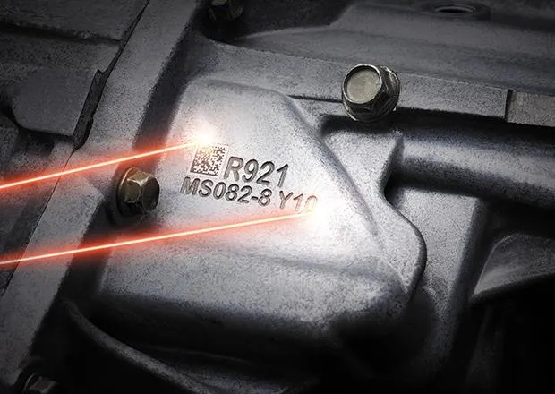
Fiber laser marking is widely suited to metal transmission components such as gears, shafts, pinions, housings and other drivetrain parts. A properly tested system can apply serial numbers, part numbers, Data Matrix codes, QR codes, production codes and assembly marks without using ink, labels or mechanical contact. For most steel and aluminum transmission parts, fiber laser is the starting technology we would evaluate first, but the final configuration depends on the material, surface treatment, marking depth, code size, part geometry and required cycle time.

LEO, JQ Laser sales engineer, with 10+ years in laser marking, cross-industry application experience, automation marking project design/implementation.
Can transmission parts be marked with a fiber laser?
Yes. Fiber laser marking is a practical option for many metal transmission components, including gears, shafts, pinions, transmission housings, bearings and other drivetrain parts. The typical requirements are permanent part identification, serial numbers, part numbers, production dates, Data Matrix codes, QR codes or assembly references. For steel and aluminum transmission components, a 1064 nm pulsed fiber laser is usually the first configuration we would evaluate. However, power alone does not determine the result. Surface finish, heat treatment, coating, available marking area, code size, required depth, part geometry and production cycle time all affect the final setup. For curved or cylindrical components, rotary fixtures or multi-axis solutions may be required.
What Transmission Parts Can Be Laser Marked?
Transmission systems contain many components with different shapes, surfaces and marking requirements. The correct fixture and laser parameters should be selected around the actual part rather than assuming that one setup will work for every component.
Transmission Gears
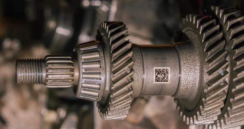
Mark gear identification numbers, Data Matrix codes, part numbers, production information and assembly references on suitable areas of the gear.
Transmission Shafts
Mark serial numbers, part IDs and traceability information on shafts using fixed fixtures or rotary marking when the mark follows a cylindrical surface.
Pinions
Small identification areas on pinions can benefit from focused laser marking where mechanical marking tools may have limited access.
Transmission Housings
Apply serial numbers, QR codes, Data Matrix codes, logos and manufacturing information to aluminum or steel housings.
Bearings
Mark identification codes, batch information and other traceability data on suitable bearing surfaces after confirming the required marking location.
Other Drivetrain Parts
Depending on material and geometry, the same marking platform can be adapted for additional powertrain and drivetrain components.
What Information Is Usually Marked on Transmission Parts?
Transmission marking is normally part identification and traceability rather than decoration. The actual marking specification depends on the customer’s manufacturing and quality system.
Unique identification for individual components or production units.
Permanent identification of part type, variant or engineering specification.
Compact machine-readable identification for traceability and production data.
Used when the application requires a larger 2D code and suitable marking space is available.
Batch, date, shift, line or process information can be incorporated into the mark.
Reference marks can help identify orientation, matching or assembly position.
Common Transmission Materials for Laser Marking
| Material | Typical Application | Possible Marking Approach | Testing Required? |
|---|---|---|---|
| Carbon / Alloy Steel | Gears, shafts, pinions | Annealing, surface marking or deeper engraving | Yes |
| Stainless Steel | Components and housings | Annealing or surface engraving | Yes |
| Aluminum | Transmission housings | Surface engraving / contrast marking | Yes |
| Heat-Treated Parts | Gears and hardened components | Parameter-dependent surface or deeper marking | Strongly recommended |
Material names alone are not enough to determine the final parameters. Alloy composition, hardness, surface treatment, coating, heat treatment and required mark depth can significantly affect the result.
Which Laser Is Suitable for Transmission Parts?
For typical metal transmission components, fiber laser is usually the first technology to evaluate. However, the final laser should be selected from the actual material and marking requirement rather than from power alone.
| Laser | Typical Use | Transmission Application |
|---|---|---|
| Fiber Laser | Metal marking and engraving | Gears, shafts, housings, pinions and many steel/aluminum components |
| MOPA Fiber | More flexible pulse control | Special surface effects, controlled contrast and selected sensitive applications |
| UV Laser | Low-heat fine marking | Selected plastics, electronic components and sensitive materials rather than typical steel gears |
| CO₂ Laser | Organic materials | Generally not the first choice for steel transmission components |
20W, 30W, 50W or 100W for Transmission Parts?
There is no universal “best” power. We normally start with the required mark type, depth, code size and cycle time, then select power around those requirements.
| Power | Typical Position | When It Makes Sense |
|---|---|---|
| 20W | Standard identification | Serial numbers, logos, part numbers and moderate marking requirements |
| 30W | General production | A practical choice when production volume or marking flexibility is higher |
| 50W | Higher throughput / deeper marking | Deeper engraving, more material removal or higher production demand |
| 100W | Heavy production | Applications where higher material removal capacity and production throughput justify the investment |
Typical Fiber Laser Configuration for Transmission Parts
| Laser Source | Raycus, JPT, MAX or other qualified fiber laser configurations depending on project requirements |
| Wavelength | 1064 nm typical for fiber laser marking |
| Available Power | 20W / 30W / 50W / 60W / 100W |
| Standard Marking Field | 110 × 110 mm typical |
| Optional Fields | 150 / 175 / 200 / 300 mm depending on lens and application |
| Marking Speed | Up to approximately 7,000 mm/s under suitable conditions; actual cycle time is application dependent |
| Cooling | Air cooling is common for standard fiber configurations |
| Software | EZCAD2 / compatible marking control software depending on configuration |
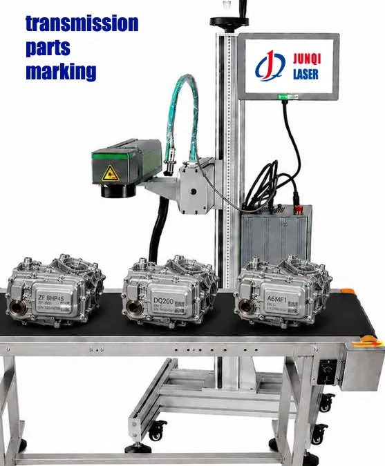
| Automation | Rotary axis, pneumatic fixture, sensor, PLC, encoder and vision inspection can be considered according to the production line |
Laser Marking Transmission Gears
Gears are not always easy to mark because of their teeth, curved surfaces and limited flat areas. The best marking position should be selected from the actual component drawing rather than simply choosing the largest available surface. For small Data Matrix codes or serial numbers, the marking area, focal distance and code size should be tested together.
For a gear that needs identification on a cylindrical or circumferential area, a rotary fixture may be appropriate. If the mark needs to follow a complex three-dimensional surface, the project may require a different optical or multi-axis configuration.
Flat Marking Area
Use a standard fixed fixture when the identification area is sufficiently flat and accessible.
Cylindrical Surface
Consider a rotary axis when the mark must follow the circumference of a shaft or round component.
Complex Geometry
Evaluate focal-height changes and optical access before deciding on a standard 2D marking head.
Data Matrix Marking for Transmission Traceability
Data Matrix is frequently considered when a transmission component needs a compact machine-readable identity. The laser itself is only one part of the system. The code must also be generated correctly, positioned consistently, marked with suitable parameters and verified with a scanner or vision system.
Typical traceability workflow
If the customer requires automated verification, a vision or code-reading system can be integrated. The exact scanner, grading method and acceptance criteria should be defined by the customer’s production and quality requirements.
Manual, Rotary or Inline Transmission Marking?
| Configuration | Best Fit | Main Consideration |
|---|---|---|
| Manual Fixture | Low to medium production | Simple loading and unloading |
| Rotary Axis | Shafts, round gears and cylindrical surfaces | Part diameter, length and required marking position |
| Pneumatic Fixture | Repeatable production | Consistent positioning and clamping |
| Automated / Inline | High-volume production | PLC, sensors, data communication, inspection and takt time |
Do not select automation only because the laser has a high maximum scanning speed. For transmission parts, actual throughput is affected by loading, fixture movement, marking time, code verification, unloading and the rest of the production cycle.
What About Heat-Treated Transmission Parts?
This is one of the areas where we recommend sample testing instead of selecting parameters from a catalog. Gears and other transmission components may be heat-treated, hardened, coated, polished or otherwise surface-finished before marking. The surface condition can change how the laser interacts with the material.
If the customer needs only identification, the goal may be a high-contrast and readable surface mark. If the mark must survive aggressive downstream processing or mechanical wear, a deeper mark may be required. The required depth should come from the customer’s actual process and durability requirement, not from an arbitrary number.
How We Test Transmission Parts Before Machine Selection
For a serious transmission marking project, a sample test is more useful than choosing a machine from wattage alone.
Receive actual parts
Confirm material & surface
Test marking parameters
Check code readability
Confirm cycle time & configuration
What should be confirmed after testing?
- Marking contrast and readability
- Data Matrix / QR code readability if applicable
- Required marking depth
- Marking position and repeatability
- Actual marking time
- Part loading and fixture time
- Surface damage or unwanted heat effects
- Compatibility with downstream manufacturing processes
Transmission Parts Laser Marking: What Should You Specify to the Supplier?
When requesting a quotation, sending only “I need a 30W laser marking machine for gears” is usually not enough. The more application information you provide, the more accurately the supplier can select the laser, lens, fixture and automation.
| Information | Why It Matters |
|---|---|
| Part drawing or photos | Determines access, fixture and marking position |
| Material and alloy | Affects laser-material interaction |
| Surface treatment | Coating, heat treatment and polishing can change the marking result |
| Marking content | Text, serial number, Data Matrix, QR or logo changes the processing requirement |
| Required depth | Determines whether surface marking or engraving is appropriate |
| Parts per hour | Helps determine laser power and automation level |
| Production integration | Determines fixture, PLC, sensor, encoder and vision requirements |
JQ Laser Reference Configuration
| Laser Type | Pulsed Fiber Laser |
| Power Options | 20W / 30W / 50W / 60W / 100W |
| Wavelength | 1064 nm |
| Marking Field | 110 × 110 mm standard; larger fields available depending on lens |
| Marking Speed | Up to approximately 7,000 mm/s under suitable conditions |
| Control | EZCAD2 / compatible system |
| Optional Integration | Rotary axis, custom fixture, pneumatic clamping, PLC, sensors, encoder and vision inspection |
JQ Laser Factory & Project Support
Jining Junqi Intelligent Technology Co., Ltd. (JQ Laser) was established in 2011 in Qufu, Jining, Shandong, China. Our work covers laser marking equipment, sample testing, machine assembly, application testing, OEM/ODM projects and customized automation.
Sample Testing
Customers can provide actual transmission components for marking tests before final machine selection.
OEM / ODM
Machine configuration, appearance, marking area, accessories, automation and documentation can be evaluated according to the project.
Quality Control
Machine configuration, laser marking performance, software operation and final marking requirements are checked before shipment.
After-Sales Support
Remote technical support, software guidance, troubleshooting, parameter assistance, sample testing and spare-parts support are available.
Lead Time, MOQ and Spare Parts
- Typical 30W fiber laser production: approximately 5–7 working days after order confirmation.
- MOQ: depends on the machine configuration, customization, packaging and OEM/ODM requirements. Standard machines and customized projects should be evaluated separately.
- Spare parts: commonly replaceable components and application-related spare parts can be discussed according to the machine configuration.
- OEM / ODM: available for suitable projects, including machine configuration, appearance, branding, automation and documentation.
Lead time and final configuration should be confirmed in the quotation because customized fixtures, automation and special components may require additional engineering time.
5 Common Mistakes When Buying a Transmission Marking Machine
1. Choosing Only by Wattage
A 50W machine is not automatically the correct solution. Marking depth, cycle time and surface condition matter.
2. Ignoring the Part Geometry
A standard 2D marking head may not be suitable when the marking surface changes significantly in height.
3. Testing Only on Flat Steel
The final transmission component should be tested, especially when it is heat-treated, coated or polished.
4. Measuring Only Laser Speed
Actual production throughput includes loading, positioning, marking, verification and unloading.
5. Forgetting Code Verification
A visually dark mark is not necessarily a reliable machine-readable Data Matrix or QR code.
Transmission Parts Laser Marking FAQ
Can a fiber laser mark transmission gears?
Yes. Fiber lasers are commonly evaluated for steel and alloy-steel transmission gears. The final parameters depend on the gear material, heat treatment, surface finish, marking depth and required contrast.
Can I mark Data Matrix codes on transmission parts?
Yes. Data Matrix is suitable for compact machine-readable identification when the code size, marking area and surface condition allow reliable decoding. The actual code should be tested and verified on the customer’s part.
Is 30W enough for transmission parts?
30W can be suitable for many identification applications, including serial numbers, part numbers and 2D codes. If deeper engraving or higher production throughput is required, 50W or 100W may be more appropriate. A sample test should determine the final configuration.
Can the machine mark cylindrical transmission shafts?
Yes. Depending on the required marking position, a rotary axis or customized fixture can be used to position the cylindrical part relative to the laser.
Can laser marking be used after heat treatment?
Potentially, but the result depends on the actual heat-treated surface. We recommend testing the finished component rather than assuming that parameters for untreated steel will produce the same result.
Can transmission marking be automated?
Yes. Depending on the production process, the marking station can be designed with fixtures, sensors, rotary systems, PLC communication, data input and optional vision or code verification.
How fast can a transmission part be marked?
There is no single cycle-time number. The actual time depends on the code or text, marking depth, material, number of passes, fixture movement and inspection requirements. A sample test is the most reliable way to establish the cycle time.
What information should I send for a quotation?
Send the part photos or drawings, material, surface treatment, marking content, code size, required depth, marking position, parts per hour and whether the process needs manual, rotary or automated loading.
Related JQ Laser Applications & Solutions
Explore broader automotive component marking applications.
Engine Parts MarkingLaser marking options for engine and powertrain components.
Automatic Rotary Laser MarkingConsider rotary solutions for cylindrical and round components.
Fiber Laser Marking MachineExplore 1064 nm fiber laser configurations for metal marking.
50W Fiber Laser Marking MachineExplore higher-power options for deeper or higher-volume applications.
Automation Marking SolutionFor integrated production-line marking and traceability.
Send Us Your Transmission Part for a Marking Evaluation
If you are comparing 20W, 30W, 50W or 100W fiber laser marking systems, do not choose the machine from power alone. Send us your part photos, material, marking content and production requirement. We can evaluate the marking approach, fixture requirements and suitable configuration before you make the purchase decision.
Request Application Evaluation